Advertisement
Quick Links
46009-0X
46009-0X
32 POINT
32 POINT
TRANSMITTER
TRANSMITTER
1
1
1
2
2
2
3
3
3
4
4
4
5
5
5
6
6
6
7
7
7
8
8
8
9
9
9
10
10
10
11
11
11
12
12
12
13
13
13
14
14
14
15
15
15
16
16
16
A
A
A
B
B
B
C
C
C
D
D
D
A1
A2
A1
RST
ACK
RST
A1
A1
ON
ON
XMT
XMT
DATA
DATA
RCV
RCV
DATA
DATA
46009-0X REV__
46009-0X REV__
1
About this Practice:
This is a new document.
Reissued Practices: Updated and
new content can be identified by a
banner in the right margin.
Issue date: April 1999
Copyright 1999 by Dantel, Inc. • Dantel is a registered trademark of Dantel, Inc. • ISO 9001 Registered
R
EMOTE
WITH
64 D
46028-XX
CONTROL POINT
1
2
3
4
5
6
7
8
9
10
11
12
13
14
15
16
A
B
C
D
A2
ACK
46028-XX REV__
2
5
Table of Contents
CAUTION
•
Install or remove modules from the shelf only when the power is off.
If you install a module in the shelf with the power on, the internal
circuitry may suffer damage and the product warranty will be void.
•
Remove and install circuit boards only in a static-safe environment
(use antistatic wrist straps, smocks, footwear, etc.).
•
Keep circuit boards in their antistatic bags when they are not in use.
•
Do not ship or store circuit boards near strong electrostatic, electromag-
netic, magnetic, or radioactive fields.
•
For more complete information on electrostatic discharge safety
precautions, refer to Bellcore
Printed in the U.S.A.
B18-05725-02
E2A A
64-
KILOBIT
46600-38 F
ISCRETE
C
ONTROLS
46020-XX
46033-XX
MULTI-ALARM
E-SYS
ADAPTER
1
2
3
4
5
6
CARRIER TEST
7
8
9
10
11
12
13
NORMAL
14
15
16
XMT
RCV
RXD
TXD
RESET
XMT DATA
DATA
XMT
46020-XX REV__
46033-XX REV__
7
8
Technical Reference # TR-NWT-000870.
TM
I
& O
NSTALLATION
PERATION
05725-02-0499 <90-00201>
S
LARM
HELF
O
,
UTPUT
IRMWARE
I
, 16
NPUTS
, N
S
O
ERIAL
46019-11
4003C
46105-XX
DUAL VF
SUMMARY
line amplifier
RCV
GND
SYNC
C/O
EXIST
NEW
XMT
ALARM
LVL
RCV
ON
OFF
ACK
MON DROP
LEVEL A
xmt
xmt
XMT
in
C/O
EXIST
NEW
ALARM
mon
RCV
ON
xmt out
OFF
ACK
CH 1
LEVEL B
loop
ACK
COMM
mon
RELAY
ALL
rcv in
CH 2
NEW
mon
C/O
EXIST
RCV
ALARM
ON
rcv out
OFF
ACK
XMT
LEVEL C
mon
MON DROP
rcv
C/O
EXIST
NEW
RCV
ALARM
LVL
XMT
ON
RCV
GND
OFF
ACK
SYNC
814003C
LEVEL D
tellabs
46105-XX REV__
46019-11 REV__
9
10
11
M
ANUAL
,
USING
48001-XX
FUSE MODULE
ALARM
1
2
3
4
5
6
7
8
9
10
11
12
13
48001-XX REV__
12
Advertisement

Related Manuals for Dantel B15-00459-02


Summary of Contents for Dantel B15-00459-02
- Page 1 For more complete information on electrostatic discharge safety precautions, refer to Bellcore Technical Reference # TR-NWT-000870. Issue date: April 1999 Copyright 1999 by Dantel, Inc. • Dantel is a registered trademark of Dantel, Inc. • ISO 9001 Registered Printed in the U.S.A.
-
Page 2: Ordering Information
ORDERING INFORMATION NOTE: 1-800-432-6835. OPTION NUMBER FEATURES B18-05725-02 64 discrete alarms, 16 control points, terminal port for access, E2A output, 64 KB digital output, cross-connect block and four 25-foot cables GENERAL DESCRIPTION ODULES Multiple Alarm Transmitters (MATs) - slots 1-2 ♦... - Page 3 GENERAL DESCRIPTION Multiple Alarm Combiner (MAC) - slot 6 Multiple Alarm Processor (MAP) - slot 7 ♦ ♦ ♦ ♦ ♦ ♦ E-System Adapter (ESA) - slot 8 ♦ ♦ Tellabs 4003C Line Amplifier - slot 9 ♦ ♦ ♦ ♦...
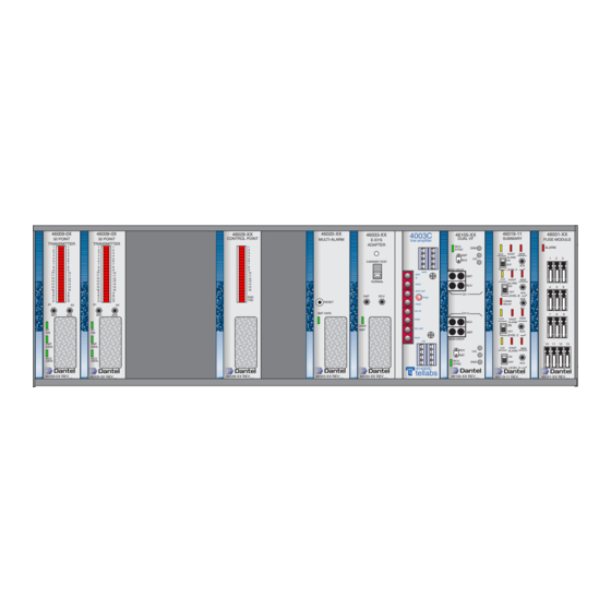
- Page 4 GENERAL DESCRIPTION Summary Alarm Module (SAM) - slot 11 Fuse Module - slot 12 . 1 - 05725-02 S HELF RONT 46009-0X 46009-0X 46028-XX 46020-XX 4003C 46019-11 46033-XX 46105-XX 48001-XX CONTROL POINT DUAL VF SUMMARY 32 POINT 32 POINT MULTI-ALARM FUSE MODULE E-SYS line amplifier...
-
Page 5: Installation
INSTALLATION • • • • • • • • • • QUIPMENT OUNTING Tools Required: ♦ ♦ ♦ ♦ 05725-02-0499 <90-00201>... - Page 6 INSTALLATION . 2 - R 05725 S IEW OF HELF LINE (ZAET Circuit) XMIT REC R T T R PANEL B PANEL D PANEL C PANEL A Connect to 64kb Channel -BATTERY Connect to 64kb Channel (Source A) (if repeater) LIST CABLS F CONNECTOR...
- Page 7 INSTALLATION . 3 - M , 41075 400-T OUNTING ONFIGURATION OUNTING IRING 64kb Channel ♦ ♦ 05725-02-0499 <90-00201>...
- Page 8 INSTALLATION . 4 - 05725 I NTERCONNECT IAGRAM 05725-02-0499 <90-00201>...
-
Page 9: Bottom Edge
INSTALLATION TRAP AND WITCH ETTINGS 46009 Multiple Alarm Transmitter (MAT) . 5 - 46009 MAT S WITCH AND TRAP OCATIONS BOTTOM EDGE 1 2 3 4 5 6 7 8 1 2 3 4 5 6 7 8 1 2 3 4 5 6 7 8 * Shown for display 5 points 1-32. - Page 10 INSTALLATION A - 46009 MAT S ABLE WITCH AND TRAP PTIONS SWITCH POSITION NOTE: A “1” indicates that the switch is up (up = OFF). A “0” indicates that the switch is down (down = ON). DCM addresses 17/18 (display 5, bits 1-32) DCM addresses 19/20 (display 5, bits 33-63) NOTE: The MATs in slots 1 and 2 are not interchangeable without changing the address on switch 5 first.
- Page 11 INSTALLATION B - 46028 CPM S ABLE WITCH AND TRAP PTIONS SWITCH POSITION NOTE: A “1” indicates that the switch is up (up = OFF). A “0” indicates that the switch is down (down = ON). 46020-38 Multiple Alarm Processor (MAP) .
- Page 12 INSTALLATION . 8 - 46020 MAP V IEWED FROM THE SWITCH 7 VIEW 1 2 3 4 5 6 7 8 ROTATED 1 2 3 4 5 6 7 8 90 DEGREES SWITCH 6 1 2 3 4 5 6 7 8 1 2 3 4 5 6 7 8 1 2 3 4 5 6 7 8 SWITCH 5*...
- Page 13 INSTALLATION 49029 RS-232 Current Loop Interface Subassembly . 9 - 49029 S WITCH AND TRAP OSITIONS 1 2 3 THRU E - 49029 S ABLE WITCH AND TRAP ETTINGS OPTION SWITCH OR STRAP SETTINGS 05725-02-0499 <90-00201>...
- Page 14 INSTALLATION 46033 E-System Adapter . 10 - 46033 E-S YSTEM DAPTER WITCH OCATIONS 1 2 3 4 5 6 7 8 1 2 3 4 5 6 7 8 1 2 3 4 5 6 7 8 1 2 3 4 5 6 7 8 = Closed OFF = Open Refer to Table G...
- Page 15 INSTALLATION G - 46033 E-S S2 S ABLE YSTEM DAPTER WITCH ETTINGS ADDRESS POSITION . . . CONTINUED 05725-02-0499 <90-00201>...
- Page 16 INSTALLATION ) - 46033 E-S S2 S ABLE CONTINUED YSTEM DAPTER WITCH ETTINGS ADDRESS POSITION . . . CONTINUED 05725-02-0499 <90-00201>...
- Page 17 INSTALLATION ) - 46033 E-S S2 S ABLE CONTINUED YSTEM DAPTER WITCH ETTINGS ADDRESS POSITION . . . CONTINUED 05725-02-0499 <90-00201>...
- Page 18 INSTALLATION ) - 46033 E-S S2 S ABLE CONTINUED YSTEM DAPTER WITCH ETTINGS ADDRESS POSITION . . . CONTINUED 05725-02-0499 <90-00201>...
- Page 19 INSTALLATION ) - 46033 E-S S2 S ABLE CONTINUED YSTEM DAPTER WITCH ETTINGS ADDRESS POSITION . . . CONTINUED 05725-02-0499 <90-00201>...
- Page 20 INSTALLATION ) - 46033 E-S S2 S ABLE CONTINUED YSTEM DAPTER WITCH ETTINGS ADDRESS POSITION 05725-02-0499 <90-00201>...
- Page 21 INSTALLATION ) - 46033 E-S S2 S ABLE CONTINUED YSTEM DAPTER WITCH ETTINGS ADDRESS POSITION 49013 202 Tone Modem Subassembly . 11 - 49013 202 T ODEM WITCH AND TRAP OCATIONS Reset, Factory use only. H - 49013 202 T ABLE ODEM WITCH AND...
- Page 22 INSTALLATION Tellabs 4003C . 12 - 4003C S WITCH AND TRAP OCATIONS 1 2 3 4 XMT* 1 2 3 4 5 6 7 8 9 10 1 2 3 4 RCV* * Transmit and Receive - channel level switches are located on front panel. Note that the settings shown are factory settings.
- Page 23 INSTALLATION I - 4003C S ABLE WITCH PTIONS SWITCH POSITION FRONT PANEL LEVEL SWITCHES J - 4003C L (S13) ABLE OOPBACK REQUENCY ELECTION FREQUENCY S13 SWITCH POSITION SET ON* * NOTE: All other S13 switch positions must be set to the OFF position.
- Page 24 INSTALLATION 46105 Dual VF 64-Kilobit Channel NOTE: Switch and strap settings for this application are indicated by a “*” in the following tables. . 13 - 46105 S WITCH AND TRAP OCATIONS CHANNEL 1 BRDG TERM RPTR LPBK 1 M LEAD 2 NO YES E LEAD TERM...
- Page 25 INSTALLATION L - 46105 S ABLE WITCH AND TRAP PTIONS STRAP POSITION DESCRIPTION SWITCH SWITCH SWITCH 05725-02-0499 <90-00201>...
- Page 26 INSTALLATION 46019 Summary Alarm Module . 14 - 46019 S WITCH AND TRAP OCATIONS Straps not shown to scale LATCH CIRCUIT "A" CIRCUIT "B" CIRCUIT "C" CIRCUIT "D" TIME SWITCH M - 46019 S ABLE WITCH AND TRAP PTIONS SWITCH POSITION 05725-02-0499 <90-00201>...
- Page 27 INSTALLATION 48001 Fuse Module . 15 - S , B11-48001 TRAP OCATION 48001-01 Fuse Module Alarm B11-48001-01 REV.__ N - JP1 S ABLE TRAP PTIONS POSITION DESCRIPTION 05725-02-0499 <90-00201>...
-
Page 28: Switch Settings
INSTALLATION UMMARY OF WITCH ETTINGS O - S ABLE UMMARY OF WITCH ETTINGS MODULE SLOT SUMMARY OF DEFAULT SWITCH SETTINGS 05725-02-0499 <90-00201>... - Page 29 TURN-UP PROCEDURE NOTE: All switches have been set at the factory for the default setting. The only changes to the switch settings are the setting of the E-System Adapter address, the configuration of alarm point level indicators, if they are required, and the setting of the MAP memory (switch 5 position 7 to ON) after configuration is complete.
- Page 30 TURN-UP PROCEDURE . 16 - T EVELS TELLABS 4003C Dantel Dantel 46033 46105 E-System 64kB Channel Adapter XMIT 0dB* Data XMT -29 dBm XMT DATA Data XMT XMT -16 dBm -29 dBm Loop XMT CLK -23 dB** 202 Tone Modem...
- Page 31 TURN-UP PROCEDURE 3 - O BSERVE THE NOTE: Some of the following sections describe level adjustment procedures. These procedures should only be required to verify suspected bad modules or to set levels on modules that have been swapped out. 2: M (MAT) LOTS ULTIPLE...
- Page 32 Synch LEDs E-SYS indicate when 46105 device is in sync ADAPTER with remote 46105 46105-XX DUAL VF 64B CHAN Data sent to SYNC MON DROP TELLABS Remote B12-49013-00 Carrier received C18-05724-XX 4003C from TNC CH 1 DATA 46105 CH 2 MON DROP TONE RCV LVL...
- Page 33 TURN-UP PROCEDURE ♦ ♦ ♦ Testing the Inputs to the MATs 5: C ONTROL OINT ODULE ♦ ♦ ♦ ♦ . . . CONTINUED 05725-02-0499 <90-00201>...
- Page 34 TURN-UP PROCEDURE Checking for correct relay operation CPM 1 DLON ALL CPM 1 DLOF ALL SLOT 6: M (MAC) ULTI LARM OMBINER SLOT 7: M (MAP) ULTI LARM ROCESSOR ♦ ♦ ♦ . . . CONTINUED 05725-02-0499 <90-00201>...
- Page 35 TURN-UP PROCEDURE Changing Default Alarm Levels UNLOCK ENTER NOTE: If a password has been entered, you will have to enter the password, and then the message.“System Unlocked” will come back . . . CONTINUED 05725-02-0499 <90-00201>...
- Page 36 TURN-UP PROCEDURE MAT 5 OPT A B C D A B C D A B C D A B C D ♦ ♦ ♦ ♦ MAT 5 OPT A A A A A A A A A A A A A A A A MAT 5 PUT NOTE: Until the PUT command is sent,the devices are not...
- Page 37 TURN-UP PROCEDURE 9: 4003C L MPLIFIER NOTE: The following steps should be only be used to verify the level settings. They should only be required if modules are swapped or to test suspected bad modules. NOTE: 2713 Hz is the factory setting. Final setting for loopback tone is set per Engineering’s instructions.
- Page 38 TURN-UP PROCEDURE 10: D VF 64 HANNEL NOTE: The following steps should be used to only verify the level settings. They should only be required if modules are swapped out or to test suspected bad modules. NOTE: Other parts of the system do not have to be functioning. .
- Page 39 TURN-UP PROCEDURE 11: S (SAM) UMMARY LARM ODULE ♦ ♦ ♦ 05725-02-0499 <90-00201>...
- Page 40 TURN-UP PROCEDURE 12: F ODULE ENERAL ROUBLESHOOTING ♦ ♦ ♦ NOTE: Additional assistance is available from Dantel’s Customer Support Services Department between the hours of 6am and 5pm Pacific time, Monday through Friday. Call 1-800-4-DANTEL (800/432-6835) 05725-02-0499 <90-00201>...
- Page 41 TURN-UP PROCEDURE SUPPORT DOCUMENTATION ♦ ♦ ♦ 05725-02-0499 <90-00201>...
-
Page 42: Imited Warranty
4. Connections between Dantel’s equipment and your equipment. 1-800-4DANTEL (1-800-432-6835). 1-800-4DANTEL Dantel, Inc. • 2991 North Argyle Avenue • Fresno, California 93727-1388 P.O. Box 55013 • Fresno, CA 93747-5013 Phone (559) 292-1111 Fax (559) 292-9355 http://www.dantel.com 05725-02-0499 <90-00201> 42 P AGES...
Need help?
Do you have a question about the B15-00459-02 and is the answer not in the manual?
Questions and answers