Table of Contents
Advertisement
Quick Links
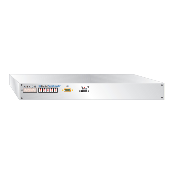
A B C D E
8
8
8
8
8
8
8
8
8
8
About this Practice:
This practice has been reissued to:
• Emphasize that RS-422 is de-
signed for point-to-point commu-
nication and RS-485 is for multi-
point communication.
Reissued Practices: Updated and
new content can be identified by a
banner in the right margin.
Issue date: August 2000
Copyright 2000 by Dantel, Inc. • Dantel is a registered trademark of Dantel, Inc. • ISO 9001 Registered
R
RemoteMaster
C1
1 2
3 4
5
Table of Contents
Ordering Information ............................................................................ 2
General Description ............................................................................... 2
Circuit Description ................................................................................ 3
Standard Installation ............................................................................. 7
Custom Installation ............................................................................. 18
Custom Configuration ......................................................................... 29
Operation ............................................................................................. 38
Circuit Board Replacement .................................................................. 42
Technical Specifications ....................................................................... 44
Warranty ............................................................................................. 46
CAUTION
•
Install or remove modules from the shelf only when the power is off.
If you install a module in the shelf with the power on, the internal
circuitry may suffer damage and the product warranty will be void.
•
Remove and install circuit boards only in a static-safe environment
(use antistatic wrist straps, smocks, footwear, etc.).
•
Keep circuit boards in their antistatic bags when they are not in use.
•
Do not ship or store circuit boards near strong electrostatic, electromag-
netic, magnetic, or radioactive fields.
•
For more complete information on electrostatic discharge safety
precautions, refer to Bellcore
Printed in the U.S.A.
46132-41
M
EMOTE
FA
FUSE
Technical Reference # TR-NWT-000870.
TM
I
& O
M
NSTALLATION
PERATION
46132-41-0800 <90-00209>>
ASTER
ANUAL
Advertisement
Table of Contents

Related Manuals for Dantel RemoteMaster 46132-41


Summary of Contents for Dantel RemoteMaster 46132-41
-
Page 1: Table Of Contents
For more complete information on electrostatic discharge safety precautions, refer to Bellcore Technical Reference # TR-NWT-000870. Issue date: August 2000 Copyright 2000 by Dantel, Inc. • Dantel is a registered trademark of Dantel, Inc. • ISO 9001 Registered Printed in the U.S.A. -
Page 2: Ordering Information
ORDERING INFORMATION NOTE: This section lists the different options available for this product. To order any of the avail- able options, contact Dantel Inside Sales through our toll-free number, 1-800-432-6835. OPTION NUMBER FEATURES B15-46132-41 RemoteMaster ; 64 discrete alarm inputs, 8 control outputs, 2 serial (TBOS) alarm interrogator... -
Page 3: Circuit Description
GENERAL DESCRIPTION Custom Installation and Custom Configuration Use these sections if your application requires parameters other than the defaults shown above. These options could include: ♦ DCP, DCPF, or TBOS protocols on either of the two re- sponder ports. ♦ Serial (TBOS) alarm polling ♦... - Page 4 CIRCUIT DESCRIPTION . 1 - F UNCTIONAL CHEMATIC For a complete list of pin-outs, OPTICALLY RXD - refer to Table A. ISOLATED INPUT RXD+ TXD - -BATT TXD + TYPICAL INPUT FOR ALL CIRCUITS ALARM INPUTS 1 - 24, 33-64 TBOS SERIAL INTERROGATOR PORT 1...
- Page 5 CIRCUIT DESCRIPTION ESPONDER ORTS Use RS-422 for point-to-point connections and RS-485 for Responder ports send alarm information to alarm reporting multi-point connections. equipment. Ports 1 and 2 can be either an RS-422/485 (default) or RS-232 interface. The RS-422/485 receive input can be terminated with 182 ohms (switch option).
- Page 6 CIRCUIT DESCRIPTION LED D UTTONS AND ISPLAY On the front panel are five push buttons and five seven-segment LED displays. Using them, you can: ♦ Configure the TABS address of the responder ports ♦ Identify the configured TABS address ♦ Query alarms or failed TBOS displays ♦...
-
Page 7: Standard Installation
STANDARD INSTALLATION he 46132-41 is designed for those applications where the user desires a minimal setup time. In order to supply that, the 46132-41 RemoteMaster is factory configured to meet the following specifications: ♦ TABS output on the two responder ports ♦... - Page 8 STANDARD INSTALLATION . 2 - D IMENSIONS 17.0" T O P R E C E S S E D F R O N T P A N E L L O C A T I O N F R O N T 3.0"...
- Page 9 STANDARD INSTALLATION . 3 - M RemoteMaster OUNTING THE FRAME RAIL STANDARD ESD LABEL ESD LABEL SCREWS ESD LABEL ESD STUD ESD STUD (OPTIONAL) ESD STUD LOCKWASHERS LOCKWASHERS STANDARD STANDARD SCREWS SCREW STANDARD SCREWS SHELF SHELF REAR FRONT SIDE VIEW FRONT VIEW IRING CAUTION:...
- Page 10 STANDARD INSTALLATION All unplated connectors, braided straps, and bus bars shall be brought to a bright finish and coated with an antioxidant before crimp connections are made. Tinned, solder-plated, or silver-plated and other plated connection surfaces do not have to prepared this way, but they shall be clean and free of contaminants.
- Page 11 STANDARD INSTALLATION IREWRAP ONNECTIONS All connections to the 46132-41 RemoteMaster except power can be made using wirewrap pins located on the back of the unit. In addition, connection to the two digital responder ports can be made using the RJ45 connectors also located on the rear of the unit.
- Page 12 STANDARD INSTALLATION . 4 - 46132-41 R EMOTE ASTER ACKPLANE -BATT 1 Port Port Port -BATT 2 RJ45 pin numbering 1. D ISCRETE LARM NPUTS Wire the discrete alarm inputs referring to Table B. PINS DESIGNATION A1 through A64 Signal Ground Return (one per alarm input) B1 through B64 Discrete Alarm Inputs 1 through 64 C25 through C32...
- Page 13 STANDARD INSTALLATION 2. C ONTROL OINTS Wire the control point relays referring to Table C. C - C ABLE ONTROL OINT ELAY UTPUTS PINS DESIGNATION C1 and C2 Control Relay #1 C3 and C4 Control Relay #2 C5 and C6 Control Relay #3 C7 and C8 Control Relay #4...
- Page 14 STANDARD INSTALLATION 5. R ESPONDER Wire Responder Port 2 referring to Table F. F - R ABLE ESPONDER RJ-2 PIN DESIGNATION RS-232 RTS or RS422/485 RX- (default) RS-232 CTS or RS422/485 RX+ (default) RS-232 TD or RS422/485 TX- (default) RS-232 RD or RS422/485 TX+ (default) RS-232 GND 6.
- Page 15 STANDARD INSTALLATION 8. W OWER Connect power to J1, located in the upper right corner of the backplane. Connect chassis ground to the ground lug located on The 46132-41 RemoteMaster provides redundent power hook- the side of the RemoteMas- ups. Two separate external power supplies can be connected to ter.
- Page 16 STANDARD INSTALLATION TABS A ETTING THE DDRESS Immediately following power-up, the following sequence of events takes place. Power On Self Test This is a self-diagnostic that the RemoteMaster performs on itself every time power is applied. This test takes approximately 3 seconds.
- Page 17 STANDARD INSTALLATION Pre-existing Configuration in Memory Press front panel buttons 1 and 2 If the 46132-41 RemoteMaster has been configured previously, at the same time during normal there are two possibilities: operation to display the configured ♦ TABS address of port 1 on the At least one responder port has been configured for TABS.
-
Page 18: Custom Installation
CUSTOM INSTALLATION his section describes those steps necessary to install the RemoteMaster in those applications where parameters are desired other than the factory defaults. Factory defaults are: ♦ TABS output on one or two digital ports ♦ 2400 baud, odd parity, 1 stop bit, 8 bit word length on both ports ♦... - Page 19 CUSTOM INSTALLATION . 7 - S WITCH AND TRAP OCATIONS POWER SUPPLY 1 2 3 4 5 6 7 8 1 2 3 4 5 6 7 8 1 2 3 4 5 6 7 8 1 2 3 1 2 3 OPEN OPEN OPEN...
- Page 20 CUSTOM INSTALLATION 2. R ESPONDER Refer to Table H to set the switches and straps for Responder Port 1. The factory setting is RS-422 terminated. H - R ABLE ESPONDER WITCH AND TRAP ETTINGS Switch 2 Switch 3 S2-1 S2-3 S2-4 S3-1 S3-2...
- Page 21 CUSTOM INSTALLATION QUIPMENT OUNTING Brackets on the side of the shelf are installed for mounting the RemoteMaster in a 19-inch equipment rack. Refer to Fig. 8 for overall dimensions of the RemoteMaster. ♦ For mounting in a 23-inch equipment rack, remove the brackets and reinstall them with the long sides extending out from the shelf.
- Page 22 CUSTOM INSTALLATION . 9 - M RemoteMaster OUNTING THE FRAME RAIL STANDARD ESD LABEL ESD LABEL SCREWS ESD LABEL ESD STUD ESD STUD (OPTIONAL) ESD STUD LOCKWASHERS LOCKWASHERS STANDARD STANDARD SCREWS SCREW STANDARD SCREWS SHELF SHELF REAR FRONT SIDE VIEW FRONT VIEW IRING CAUTION:...
- Page 23 CUSTOM INSTALLATION Multiple connectors shall not be secured by the same bolt assembly. Any unplated connection surfaces used (if any) that are part of a grounding or bonding path shall be brought to a bright finish and coated with an antioxidant before being electrically connected. All grounding and bonding conductors shall be connected by exo- thermic welding or compression type fittings to the greatest extent possible.
- Page 24 CUSTOM INSTALLATION K - P ABLE ESIGNATIONS ROW/PIN DESIGNATION ROW A A1 - A64 Signal return ground for discrete alarms 1 through 64 ROW B B1 - B64 Discrete alarm inputs 1 through 64 ROW C C1 - C16 Control point relays (C1-C2, C3-C4, C5-C6, and so on) C17 - C20 Serial (TBOS) interrogator port #1 C21 - C24...
- Page 25 CUSTOM INSTALLATION . 10 - 46132-41 R EMOTE ASTER ACKPLANE -BATT 1 Port Port Port -BATT 2 RJ45 pin numbering 1. D ISCRETE LARM NPUTS Wire the discrete alarm inputs referring to Table L. L - D ABLE ISCRETE LARM NPUTS PINS DESIGNATION...
- Page 26 CUSTOM INSTALLATION 2. C ONTROL OINTS Wire the control point relays referring to Table M. M - C ABLE ONTROL OINT ELAY UTPUTS PINS DESIGNATION C1 and C2 Control Relay #1 C3 and C4 Control Relay #2 C5 and C6 Control Relay #3 C7 and C8 Control Relay #4...
- Page 27 CUSTOM INSTALLATION 5. R ESPONDER Wire Responder Port 2 referring to Table P. P - R ABLE ESPONDER DESIGNATION RS-232 RTS or RS422/485 RX- (default) RS-232 CTS or RS422/485 RX+ (default) RS-232 TD or RS422/485 TX- (default) RS-232 RD or RS422/485 TX+ (default) RS-232 GND 6.
- Page 28 CUSTOM INSTALLATION 8. W OWER Connect chassis ground to Connect power to J1, located in the upper right corner of the the ground lug located on backplane. the side of the RemoteMas- The 46132-41 RemoteMaster provides redundent power hook- ter. Do not connect chassis ups.
-
Page 29: Custom Configuration
CUSTOM CONFIGURATION n most cases, the 46132-41 Remotemaster will require little, if any changes to the factory default settings. In those situations where parameters or features are desired that differ from the factory default, the RemoteMaster must be configured with an Ascii terminal before it will operate properly. - Page 30 CUSTOM CONFIGURATION Pre-existing Configuration in Memory If port 1 has been configured for If the 46132-41 RemoteMaster has been configured previously, TABS protocol, press front panel there are two possibilities: buttons 1 and 2 at the same time ♦ during normal operation to display At least one responder port has been configured for TABS.
- Page 31 CUSTOM CONFIGURATION ONFIGURATION SING A ERMINAL Apply power to the RemoteMaster and the Ascii terminal or com- puter. Press push button 5 on the front of the RemoteMaster. The RemoteMaster’s configuration appears on the terminal screen. The screen displays the current configurations of the eight interrogator (TBOS) and three responder ports, and the status of the expansion board.
- Page 32 CUSTOM CONFIGURATION R - C ABLE ONFIGURATION ORKSHEET INTERROGATOR PORTS Port # Display Display Display Display Display Display Display Display RESPONDER PORTS Port # Display Display Display Display Display Display Display Display NOTES: 1. Mark the Interrogator Ports charts with the displays you will use. 2.
- Page 33 CUSTOM CONFIGURATION . 13 - A LARM APPING Discrete Alarms and Interrogator Ports Responder Port Discrete and Base Address Control Points DCP/DCPF Base Address +1 TBOS Displays 1-16 (ports 1 & 2) Display 0 Discrete Points Display 1 TABS Control Points Displays 2 through 17 TBOS Displays 1-16 (ports 1 &...
- Page 34 With DCP protocol, certain address combinations result in reporting failures. The problem, a loss of synchronization in the addressing sequence, is inherent in DCP. Dantel recommends DCPF protocol because it maintains synchronization. Configuring a responder port for TBOS protocol: Type 2 from the configuration screen to display the responder port prompts.
- Page 35 CUSTOM CONFIGURATION SELECT PORT NUMBER - Type the port number to be configured. Valid entries are 1, 2, or 4 (port 4 is not used). For the following selections, type S or press ENTER to skip to the next selection, type F to save changes and exit the port configura- tion, or type Q to quit the port configuration without saving any changes.
- Page 36 CUSTOM CONFIGURATION SELECT STOP BITS - Set for 1. Type 1 if the stop bits are not set for SELECT RTS/CTS HANDSHAKE - Default is 1 (OFF). Typing 2 enables RTS/CTS handshaking. Changing the value, typing S or F, or pressing ENTER saves any changes and brings up the configu- ration screen.
- Page 37 CUSTOM CONFIGURATION CTIVITY Button 2 shows the activity of the interrogator and responder ports on the LED display. Press the button repeatedly to cycle through the ports sequentially to the port you want to monitor. The LED display shows the activity of the selected port. To return to the alarm mode, press button 1.
-
Page 38: Operation
OPERATION mmediately following power-up, the following sequence of events takes place. Power On Self Test This is a self-diagnostic that the RemoteMaster performs on itself every time power is applied. This test takes approximately 40 seconds. After the POST, there are two possible situations: ♦... - Page 39 OPERATION If at least one responder port has been configured for TABS, following the Power On Self Test the front panel will display the If port 1 has been configured for TABS protocol, press front panel current TABS address. Press buttons 1 or 2 to change the buttons 1 and 2 at the same time address if desired.
- Page 40 OPERATION LARM OCATION Press button 3. The RemoteMaster scans all alarm points, stopping when an active alarm is reached. Read the display as follows: Pxyzz where P = TBOS port x = TBOS port number (1-8) y = Display number within port zz = Point number within display -or- D zz...
- Page 41 OPERATION YSTEM ESET Press buttons 1, 3, and 5 simultaneously on the front panel for two seconds. TABS A DDRESS ETRIEVAL Press buttons 1 and 2 simultaneously on the front panel to display the configured TABS address for port 1. (Applicable only if port 1 is configured for TABS protocol.) LED T Press buttons 1 and 3 simultaneously.
-
Page 42: Circuit Board Replacement
CIRCUIT BOARD REPLACEMENT he wiring on the RemoteMaster does not have to be removed to replace the circuit cards inside the unit. To Remove the RemoteMaster Main Board Remove the plastic safety cover on the rear by unscrewing the two fastener screws. - Page 43 CIRCUIT BOARD REPLACEMENT . 15 - L OCATION OF EMOTE ASTER OARD POWER SUPPLY 1 2 3 4 5 6 7 8 1 2 3 4 5 6 7 8 1 2 3 4 5 6 7 8 1 2 3 1 2 3 OPEN OPEN...
-
Page 44: Technical Specifications
TECHNICAL SPECIFICATIONS DESCRIPTION VALUE Input Voltage -21 to -56 VDC Input Current, max. (+15%) @ -21 VDC 349 mA @ -24 VDC 328 mA @ -48 VDC 239 mA @ -56 VDC 229 mA Heat Dissipation, max. (+15%) @ -21 VDC 27.4 Btu/Hr @ -24 VDC 29.4 Btu/Hr... - Page 45 TECHNICAL SPECIFICATONS . . . CONTINUED DESCRIPTION VALUE Responder Ports Number available Protocols DCP, DCPF, TBOS, TABS Interfaces RS-232, RS-422/485 Data Rates 300, 600, 1200, 2400, 4800, and 9600 baud Configuration Port Communications ASCII Interface RS-232 Data Rate 9600 baud Change-of-State (COS) Relay Contact Type Normally Open, Dry Contact...
-
Page 46: Warranty
To ensure expedient processing of your order, provide a purchase order number and shipping and billing information when requesting an RMA number. Also, when the units are returned to Dantel, include a descrip- tion of the failure symptoms for each unit returned. Send defective equipment to: Dantel, Inc.
Need help?
Do you have a question about the RemoteMaster 46132-41 and is the answer not in the manual?
Questions and answers