Advertisement
Quick Links
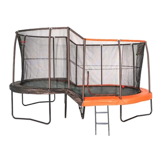
10FT x 17FT OVAL LEVELING
TRAMPOLINE & ENCLOSURE
Model# JKLCOV1017C4
90
200
Got a Problem building your trampoline?
Please contact us at contact@jumpking.com
WARNING: Read these assembly instructions carefully
before attempting to assemble or use this product. Keep
this user guide in a safe place for future reference.
Jumpking
3970 Lindbergh Drive Addison, TX 75001
®
Advertisement

Related Manuals for Jumpking JKLCOV1017C4


Summary of Contents for Jumpking JKLCOV1017C4
- Page 1 TRAMPOLINE & ENCLOSURE Model# JKLCOV1017C4 Got a Problem building your trampoline? Please contact us at contact@jumpking.com WARNING: Read these assembly instructions carefully before attempting to assemble or use this product. Keep this user guide in a safe place for future reference.
- Page 3 10FT x 17FT OVAL LEVELING TRAMPOLINE & ENCLOSURE If you have questions after reading this manual, please email us at contact@jumpking.com. Trained technicians will provide immediate assistance. PART LIST More detailed instructions on assembling your trampoline will be available on www.jumpking.com...
- Page 5 www.jumpking.com.
- Page 6 Please visit our website at www.jumpking.com Please visit our website at www.jumpking.com Please visit our website at www.jumpking.com...
- Page 7 If you have questions after reading this manual, please visit our websites at www.jumpking.com.
- Page 16 Top rail with “B” Marking Top rail with “D” Top rail with “C” Top rail with “E” Top rail with “A” Marking (Note: Connector “F” marking Marking Marking Marking Part number: ML1017A is already pre-assembled on these Part number: ML1017D Part number: ML1017C Top rails) Part number: ML1017E...
- Page 17 Enclosure Top Enclosure Foam Poles Sleeves Enclosure Pole Caps Enclosure Pole Caps (Note: These Foam sleeves (Note: Foam sleeves are 11.2-32 Black color 10.5-32 Grey color are already pre-assembled already pre-assembled (Note: These Caps are (Note: These Caps are on enclosure poles) on top enclosure poles) Enclosure Netting already pre-assembled...
- Page 18 Lay out the Top rails and Corner legs parts in groups: 1) Top rail with B marking: 2 pcs, 2) T-connector with F marking: 4 pcs (already pre-assembled to Top rail B), 3) W leg (Corner legs) with K marking: 2 pcs, 4) Leg extension with reduction for upper level (corner legs) L marking: 4 pcs.
- Page 19 Lay out the T-connector with G and H markings: Insert T-connectors G marking (Right side) and H marking (Left side). *Note: Plastic Mallet may be required to push parts in (Not included). Lay out the Upper level middle leg parts in group: Leg extension with Reduction “N”...
- Page 20 Insert one side of the leg into Insert remaining side of the Connector H marking leg into Connector G marking using 1 self tapping screw. using 1 self tapping screw. Please ensure to indicate to insert the screw into one side first then go to other side.
- Page 21 Lay out the Lower level middle leg parts in group: Leg extension with Reduction “Q” Marking for Lower level: 2 pcs, 2) Curve leg extension with “R” Marking for Lower level: 2 pcs, 3) Leg center for Lower level “S” Marking: 1 pc, 4) Self tapping screw (Part 21): 4 pcs.
- Page 22 Insert Top rail E marking: 2 pcs. *Note: Plastic Mallet may be required to push parts in (Not included). Lay out the remaining Top rails and Corner legs parts in groups: 1) Top rail with B marking: 2 pcs, 2) T-connector with F marking: 4 pcs (already pre-assembled to Top rail B), 3) W leg (Corner legs) with K marking: 2 pcs, 4) Leg extension with reduction for lower level(corner legs) M marking: 4 pcs.
- Page 23 Connect both sections together. *To close the frame both people must push against each other until it is connected. The frame has been assembled.
- Page 24 Warning label facing up Locate the V-rings with Green webbing for upper level of trampoline. Green webbing UPPER LEVEL These will be at 180 to each other with Orange webbing for lower level of trampoline. Orange webbing LOWER LEVEL Closed Open IMPORTANT: Identify the closed end of the spring and the open end of the spring for...
- Page 25 Green webbing Upper level Orange webbing Lower level Insert the Closed end of one spring Part 26, onto one of the webbings Green and Orange stitched V-Rings as shown. IMPORTANT: Correct Spring direction must be utilized to ensure a secure attachment as shown above. Insert the Open end of the spring into corresponding spring slot (location 1) in the top of the frame.
- Page 26 Upper level 13 14 15 16 Lower level IMPORTANT: Follow the number sequence accordingly to prevent the overstretching of springs.
- Page 27 Upper level Lower level IMPORTANT: Follow the number sequence accordingly to prevent the overstretching of springs.
- Page 28 Upper level Lower level IMPORTANT: Follow the number sequence accordingly to prevent the overstretching of springs.
- Page 29 During this step, you will stop attaching the 10 inch springs. Then 1 person will push down the jumping mat, the 2nd person will attach the 3 sets of Strap, Carabiner and Special spring 3.5 inch to the leg frame. You need the following parts to complete this step: 3 x Carabiner - Part 22 3 x 3.5 Inch Spring - Part 23...
- Page 30 Upper level Lower level After the springs underneath have been attached, continue attaching the springs (part 26) on remaining top rails. IMPORTANT: Follow the number sequence accordingly to prevent the overstretching of springs.
- Page 31 Upper level Lower level IMPORTANT: Follow the number sequence accordingly to prevent the overstretching of springs.
- Page 32 Upper level Lower level Attach the remaining springs to the top rails according to the number sequence shown in the above images. IMPORTANT: Follow the number sequence accordingly to prevent the overstretching of springs. The stitched mat is now fitted. NOTICE: The trampoline should not be moved.
- Page 33 PAD for Upper level is Black color. Lay the frame pad - Upper level - Part 28 and Lower level - Part 29 out over the edge of the frame with the ties facing downwards. PAD for Lower level is Orange color. Tie the outer elastic straps on the underside of the frame pad around the top tubes of the frame.
- Page 34 Bottom enclosure poles ) You will need the following parts to complete step 4: 12 Enclosure bottom poles - Part 30, 12 Enclosure top poles - Part 31, 12 Self tapping screws - Part 21. *Note: Foam sleeves already pre-assembled on Top and bottom poles.
- Page 35 Insert the bottom enclosure tube into the tubes in the T-connector+welded tubes visible through the slots in the frame pad. Assemble middle Enclosure poles first with Black Color caps: Part#33 Black color...
- Page 36 Assemble remaining Enclosure poles first with Grey Color caps: The enclosure poles are now fitted and you have completed step 4.
- Page 37 You will need the following parts to complete step 5: 1 x Enclosure netting - Part 35 1 x G3 FRP poles with Green marking - Part 37 1 x G3 FRP poles with Red marking - Part 38 2 x G3 FRP bent poles with Yellow marking - Part 39 G3 FRP poles G3 FRP poles for Lower level...
- Page 38 Insert the G3 FRP poles (Green marking) through the sleeves on the top of the enclosure netting for UPPER LEVEL Black tunnel. Then insert the G3 FRP poles (Red marking) through the sleeves on the top of the enclosure netting for LOWER LEVEL Orange tunnel.
- Page 39 Insert the G3 FRP poles (Yellow marking) into the tunnel sleeve on top center of enclosure mesh. Connect the Bent metal connector between the G3 FRP poles (Yellow marking) and G3 FRP poles (Green marking) on upper level and (Red marking) on lower level then close the velcro flap.
- Page 40 ’ Attach the 11 other exposed sections of the G3 FRP poles to the other enclosure tubes in the order shown in the diagram. The enclosure net is now fitted and you have completed step 5.
- Page 41 You will need the following parts to complete step 6: 8 x Cords - Part 36...
- Page 42 STEP 7: ATTACHING THE ACCESSORIES GAMES Lay out the accessories games: Part 40 1 x Basketball mesh - Part 40, Part 43 1 x Target game - Part 41, 10 x Black metal screws (Include 2 for spare Part 41 use) - Part 42, 1 x Inflater and plastic needle - Part 43, Part 44...
- Page 45 12 14 Leg center P marking Top rails with A marking Leg extension Q marking Top rails with B marking Curve leg extension R Top rails with C marking marking Top rails with D marking Leg center S marking Top rails with E marking XPE foam Connector with F marking Self tapping screw...
- Page 46 Set of G3 FRP Red marking G3 bent FRP Yellow marking Basketball mesh game Target game To order replacement parts, visit our website or email us at contact@jumpking.com. To help us assist you, please provide the following information when contacting us:...
Need help?
Do you have a question about the JKLCOV1017C4 and is the answer not in the manual?
Questions and answers