Advertisement
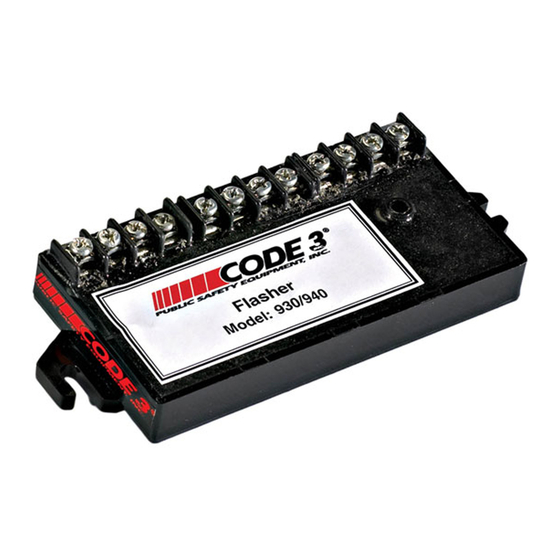
MODELS 930 & 940 FLASHERS
Contents:
Introduction ......................................................... 2
Unpacking & Pre-Installation .............................. 2
Installation & Mounting ....................................... 3
Terminal Functions ............................................. 3
Flasher Installation ............................................. 4
Testing the Flasher ............................................. 6
Warranty ............................................................. 8
Advertisement
Table of Contents

Subscribe to Our Youtube Channel
Related Manuals for Code 3 930


Summary of Contents for Code 3 930
- Page 1 MODELS 930 & 940 FLASHERS Contents: Introduction ............2 Unpacking & Pre-Installation ......2 Installation & Mounting ........3 Terminal Functions ..........3 Flasher Installation ..........4 Testing the Flasher ..........6 Warranty ............. 8...
- Page 2 OF EMERGENCY PERSONNEL AND THE PUBLIC. Unpacking & Pre-installation After unpacking your 930 or 940 Flasher, carefully inspect the unit and associated parts for any damage that may have been caused in transit. Report any damage to the carrier immediately.
- Page 3 Installation & Mounting Mounting Methods The units can be mounted using either the mounting tabs located at each end of the unit or the mounting hole through the unit. Larger wires and tight connections will provide longer service life for components. For high current wires it is highly recommended that terminal blocks or soldered connections be used with shrink tubing to protect the connections.
- Page 4 Supplies Outputs +12VDC. The Unit should be fused with a user supplied 20 amp. fuse and wired with #14 AWG wire minimum. To install the Model 930 as an Alley Light flasher, refer to Figure 1 while following the steps below: NOTE: Use #14 AWG wire (minimum) for all connections.
- Page 5 Flasher Unit. This switch will override the flash feature and cause the Right Alley Light to operate in steady burn mode. If you are installing the Model 930 flasher, proceed to Testing the Flasher on Page 6. If you are installing flasher Model 940 continue with step 11 below.
- Page 6 Install the 20 amp. fuse in the in-line fuse holder. Turn ON the switch connected to terminal 2. The Alley lights will flash (Wig/Wag) at 90 FPM. Turn ON the switch connected to terminals 3. The Right Alley light will change to steady burn mode.
- Page 8 If a product must be returned for repair or replacement*, please contact our factory to obtain ® a Return Goods Authorization Number (RGA number) before you ship the product to Code 3 Inc. Write the RGA number clearly on the package near the mailing label. Be sure you use sufficient packing materials to avoid damage to the product being returned while in transit.
Need help?
Do you have a question about the 930 and is the answer not in the manual?
Questions and answers