
Related Manuals for All American Scoreboards MP-2215


Summary of Contents for All American Scoreboards MP-2215
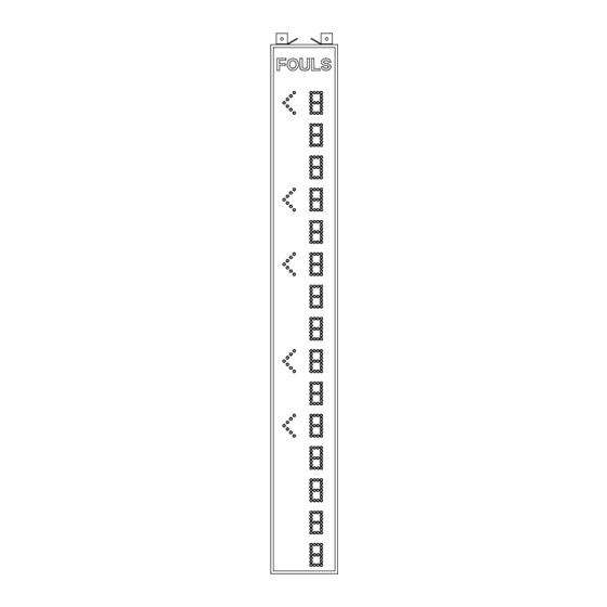
- Page 1 OPERATING INSTRUCTIONS AND SERVICE MANUAL BASKETBALL PLAYER FOULS PANELS MODEL MP-2215 EFFECTIVE S.N.XXXX, APRIL 1,1987...
-
Page 2: Table Of Contents
TABLE OF CONTENTS GENERAL INFORMATION DESCRIPTION IDENTIFICATION DAMAGE DAMAGE CLAIM PROCEDURE INSTALLATION GENERAL INFORMATION INSPECTION PRE-TEST DATA CABLE INSTALLATION ELECTRICAL CONNECTIONS CONTROL CONSOLE OPERATION DISPLAY POWER CONSOLE POWER CONSOLE DISPLAY PLAYER NUMBERS PLAYER FOULS ENTRY PLAYER IN GAME ENTRY / SUBSTITUTION MAINTENANCE AND TROUBLESHOOTING INTRODUCTION TEST EQUIPMENT... -
Page 3: General Information
1. GENERAL INFORMATION 1.1 DESCRIPTION Your All-American scoreboard has been carefully inspected and tested before leaving the factory. It is possible, however, that components may be loosened or forced out of adjustment in transit. If this occurs, follow the troubleshooting guide (section 4). If equipment then fails to operate, contact immediately: ALL-AMERICAN Service Department EVERBRITE Corporation... -
Page 4: Damage Claim Procedure
? ft Control Cable (if ordered) IMPORTANT! The MP-41 cable supplied by ALL AMERICAN SCOREBOARDS for use on the Microprocessor based scoreboards is specifically designed for this system. Use of a substitute cable may void the warranty on the scoreboard! -
Page 5: Inspection
2.2 Inspection Inspect each unit and tighten all screws, lamps, and fittings that may have loosened in shipment. 2.3 Pre-Test Before installing the displays, pre-test all functions. (A) Connect the displays to a 20 AMP, 120 Volt AC circuit. (B) Plug the control console into the top of the displays. (C) Test operate all functions on each display according to the operating instructions in section 3 of this manual. -
Page 6: Control Console Operation
3. CONTROL CONSOLE OPERATION 3.1 Fouls Panel Display Power Turn on the branch circuit to the displays. The displays will be blank. 3.2 Console Power Plug the control console cable into the wall junction box. Push ON/OFF once to turn the console on. Push ON/OFF a second time to shut the console off. -
Page 7: Player Fouls Entry
Repeat the procedure for the guest foul panel. To clear the entire panel, push: PANEL CLEAR 3.5 Player Foul Entry Once the player numbers have been entered it is very simple to enter the foul information. Example: Player number 14 receives his/her first foul. Push: PLAYER NO. -
Page 8: Troubleshooting
4.3 Troubleshooting Whenever possible, follow the troubleshooting guides prior to contacting the customer service department. If a problem not described in the guides exists, contact the customer service department immediately. Refer to the diagrams provided for assistance in troubleshooting scoreboard malfunctions. 4.4 Troubleshooting Guides (A) Scoreboard doesn't light and console doesn't work (a) Check that the main power switch is turned on. - Page 9 instructions on long cable compensation. If the voltage is between 8 VAC and 12 VAC contact the customer service department. (D) The scoreboard digits light, the console works, but there is no control of the scoreboard. (a) Check the voltage between the black and red wires in the junction box with a voltmeter set on the 3 VDC or higher scale.
-
Page 10: Replacement Parts List
5. REPLACEMENT PARTS LIST 5.1 Scoreboard Display Parts... - Page 11 1 DISPLAY ASSEMBLY REPLACEMENT PARTS LIST (MP-2215)
-
Page 12: Diagrams
fig.& MFG PART VENDOR index NUMBER DESCRIPTION PART # 153006 Display Assembly 153006 151283 Face, Red Plex. 151283 150366 Receiver PCB Assembly 150366 *** PROGRAM *** 151485 Driver Assy, 3 Digit Display A3-A6 151485 703719 Transformer, MP 12V/18V C-1106 350050 Transformer, 12V/8A C-1082 705075... - Page 13 CONSOLE KEYBOARD 6.2 Scoreboard System Layout...
- Page 14 SYSTEM LAYOUT 6.3 Junction Box Wiring...
- Page 15 JUNCTION BOX WIRING...
- Page 16 6.4 Fouls Panel Wiring...
-
Page 17: Fouls Panel Wiring
FOULS PANEL WIRING Installation Drawing INSTALLATION DRAWING...
Need help?
Do you have a question about the MP-2215 and is the answer not in the manual?
Questions and answers