
Related Manuals for Roger PR402


Summary of Contents for Roger PR402
- Page 1 PR402EN.doc PR402 v1.0 INGLE CCESS ONTROLLER 117.0 IRMWARE VERSION Installation Manual...
-
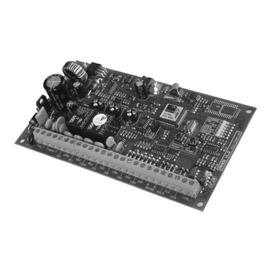
Page 2: General Description
General Description The PR402 controller is dedicated for use in Access Control and Time & Attendance systems. It may be configured to perform both function simultaneously or exclusively. Controller is equipped with switched mode power supply circuit adopted for operation with sealed gel type battery. - Page 3 Single Door Operation PR402 may operate with two identification access points (access terminals), first located on EXIT side and second located on ENTRY side of the door. As a default an EXIT terminal has address ID=1 where ENTRY terminal has address ID=0 (this assignments refer to PRT series readers).
- Page 4 Some brands of power supply are equipped with such a output line (e.g. PS20N from Roger). After input line is triggered controller generate [AC lost alarm ON] event, when line returns to normal condition controller generates [AC lost alarm OFF] event.
- Page 5 PR402EN.doc Besides those listed above functions input lines can be configured to customer defined input functions. Using PC software installer may define new input line functions, definition of input line function consist from function name and function code. Function name can be used to distinguish purpose of input e.g.
- Page 6 Card . In case the Card+PIN mode is active, controller requires use of both forms of identification (PIN and Card) in any sequence (Card then PIN or reverse sequence). PR402 accepts PINs consisting from 3 up to 6 digits and Cards (proximity transponders). The type of card is not determined it depend of type of reader connected to controller’s Clock &...
- Page 7 Operation with XM-8 module The PR402 may operate with one or two remote XM-8 I/O modules connected to controller via Clock and Data lines. PR402 enable operation with XM-8 as elevator control interface. The first XM-8 module (address ID=8) is dedicated to control access to floor 1-8, the second one (address ID=9) controls access to floors 9-16.
- Page 8 T&A Registration The PR402 offers T&A registration which further can be used for calculation of total job hours. Each [Access granted] event which occur on controller have a T&A Mark (T&A status) which specifies what kind of entry/exit has been registered. The actual type of registration for T&A purposes is determined by controller’s T&A Mode.
-
Page 9: Installation
Roger recommend to ground power supply minus. PR402 can not be mounted in external location, it hasn’t any protection against moisture, rain or cold, only indoor location are acceptable. Note: You must complete all wiring before applying AC supply to controller. - Page 10 PR402EN.doc AC input, terminals: AC The panel requires 18-22V 30VA transformer. Connect the primary side of transformer to unswitched AC source and secondary side to AC terminals. Note: Do not connect transformer until all other wiring is complete. Auxiliary Power Output, terminals: +AUX- These terminals provide up to 1A of additional current at 12V DC for devices requiring power.
-
Page 11: Memory Reset Procedure
Roger team constantly working on functionality enhancements so new firmware versions are released quite often (every new firmware version is published on www.roger.pl). Our customers are advised to register at web site so Roger will let inform when new versions are ready for download. - Page 12 OPEN Door Lock energized CLOCK BELL Button SYSTEM When pulsing controller wait for SWITCHER type identifier ERROR Memory Error TAMPER Tamper Loop Exit Button Door Lock DATA CLOCK Expander Module e.g. XM-2 / XM-8 Typical wiring diagram of PR402 Cdr109EN...
- Page 13 IN4 input line is reserved for communication purpose with mentioned readers and can not be use for other purposes. DATA CLOCK Additional Modules e.g. XM-2/XM-8/PSAM-1 Typical wiring diagram of PR402 when operating with Wiegand type readers Cdr142EN...
- Page 14 IN1..IN4 Door Lock Door Lock Controller “A” Controller “B” Input line must be configured as: “Door contact” NC type PR402: Wiring diagram for INTERLOCK configuration (when door “A” became open access on controller “B” is disabled and vice verso). Cdr141EN...
- Page 15 - Selects Entry or Exit door lock - Access terminal supply CLK/DTA - Communication interface EXIT ENTRY EXIT TERMINAL ENTRY TERMINAL ADDRESS ID=1 ADDRESS ID=0 Using PR402 for separate Entry/Exit door control. The same method can be implemented for rotary gate (TRIPOD) control . cdr139EN...
- Page 16 R o g e r A c c e s s C o n t r o l S y s t e m An example of RACS system which incorporate 15 access controllers, CPR control panel and 3 power supplies. Note ! When system is supplied from more then one supply source, all minuses of all supplies...
- Page 17 R o g e r A c c e s s C o n t r o l S y s t e m T h e s t r u c t u r e o f R A C S v . 4 CPR32 Access Access...
Need help?
Do you have a question about the PR402 and is the answer not in the manual?
Questions and answers