Table of Contents
Advertisement
Quick Links
Roger Access Control System
User manual for
CPR32-SE-BRD v3.0 network controller
Firmware version: 3.0.5133 or newer
Hardware version: 3.0
Document version: Rev. B
© 2016 ROGER sp. z o.o. sp.k. All rights reserved. This document is subject to the Terms of Use in their current version published at
the
www.roger.pl
website of the Roger sp. z o.o. sp.k. company (hereinafter referred to as ROGER).
Advertisement
Table of Contents

Related Manuals for Roger CPR32-SE-BRD


Summary of Contents for Roger CPR32-SE-BRD
- Page 1 Hardware version: 3.0 Document version: Rev. B © 2016 ROGER sp. z o.o. sp.k. All rights reserved. This document is subject to the Terms of Use in their current version published at www.roger.pl website of the Roger sp. z o.o. sp.k. company (hereinafter referred to as ROGER).
-
Page 2: Table Of Contents
CPR32-SE-BRD v3.0 User Manual 2020-10-08 Contents 1. Introduction ........................3 1.1 This manual ........................3 2. Description and Specification ..................3 3. Installation ........................4 3.1 Terminals and connection diagram ..................4 3.2 LED indicators ........................6 3.3 Power supply ........................6 3.4 Communication with CPR .................... -
Page 3: Introduction
Functional description of PRxx2 series controllers Functional description of PRxx1 series controllers PR Master User manual Due to hardware differences the previous version of CPR i.e. CPR32-SE-BRD v2.0 is described in separate manual. 2. D ESCRIPTION AND... -
Page 4: Installation
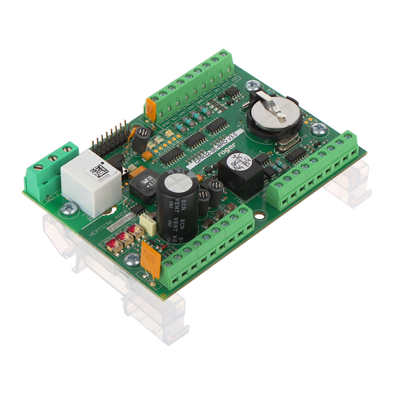
CPR32-SE-BRD v3.0 User Manual 2020-10-08 Weight approx. 100g Certificates 3. I NSTALLATION 3.1 Terminals and connection diagram Fig. 1 CPR32-SE-BRD v3.0 network controller Table 2. CPR32-SE-BRD v3.0 terminals Terminal Description Terminal Description BAT+ Backup battery Ground BAT- Backup battery IN7 input line... - Page 5 CPR32-SE-BRD v3.0 User Manual 2020-10-08 Fig. 2 Typical connection diagram for CPR32-SE-BRD v3.0 network controller 5/15...
-
Page 6: Led Indicators
3.2 LED indicators According to fig. 3, CPR32-SE-BRD v3.0 is equipped with 5 LED indicators and RESET button (S1) on its PCB. RESET button can be used to restart the CPR in the same way as in case of powering device off and then on. - Page 7 CPR32-SE-BRD v3.0 User Manual 2020-10-08 Fig. 4 CPR32-SE-BRD v3.0 and PR402DR/PR411DR controllers supplied with 18VAC Fig. 5 CPR32-SE-BRD v3.0 and PRxx1/PRxx2 series controllers supplied with 12VDC 7/15...
-
Page 8: Communication With Cpr
CPR32-SE-BRD v3.0 network controller. Single RS485 bus creates network (subsystem) including single CPR32-SE-BRD v3.0 unit and up to 32 access controllers. For the communication with distant subsystems it is required to use UT-4DR or UT-4 v2.0 communication interface as both enable communication through computer network (LAN or WAN). -
Page 9: Installation Guidelines
By default the next step consists in detection of controllers on RS485 bus which requires selection of Controllers button and then Add button in Networks window. When all opened windows are closed, CPR32-SE-BRD device shall be listed in the main window of PR Master software – see fig. 7 Fig. - Page 10 Menu: Settings->Options In the window opened by means of this option, the administrator can activate/deactivate power supply tests and internal tests of CPR32-SE-BRD unit as well as switch the CPR off and on. Menu: Settings->Inputs/Outputs In the window opened by means of this option it is possible to assign functions to CPR32-SE-BRD inputs and outputs.
- Page 11 (network). [12] Clear all alarms When the input is activated then all alarms in monitored CPR32-SE-BRD and controllers within particular in subsystem subsystem (network) are cleared. The function [12] operates as a sum of [01] and [13] functions. [13]...
- Page 12 The output remains activated until the problem is eliminated. [77] CPR on The output signals that CPR32-SE-BRD is switched on by PR Master software. [78] CPR off The output signals that CPR32-SE-BRD is switched off by PR Master software.
-
Page 13: Memory Reset
After a few seconds the CPR shall restart automatically and switch to normal mode 4.3 Firmware update The latest versions of firmware and Roger ISP software are available at www.roger.pl. In order to update firmware it is necessary to connect the device by means of RS485 bus to communication interface (UT-2USB or RUD-1) and then connect the interface to PC with installed Roger ISP software. -
Page 14: Problem With Erratic Jumps Of Mouse Cursor In Windows Os
(erratically jumps around screen) and PR Master software reports serial port error. Note: The problem, which is described above is not caused by CPR32-SE-BRD but it results from commonly known Windows fault and it cannot be corrected by Roger engineers. -
Page 15: Product History
CPR32-SE-BRD v3.0 User Manual 2020-10-08 6. P RODUCT HISTORY Table 8. Product history Product version Released Description CPR32-SE-BRD v.1.0 01/2007 The first commercial version of the product CPR32-SE-BRD v.2.0 11/2009 The next hardware version CPR32-SE-BRD v.3.0 01/2017 New electronic module based on PR402DR...
Need help?
Do you have a question about the CPR32-SE-BRD and is the answer not in the manual?
Questions and answers