Table of Contents
Advertisement
Advertisement
Table of Contents

Related Manuals for Datacolor ELREPHO


Summary of Contents for Datacolor ELREPHO
- Page 1 Datacolor Datacolor ELREPHO User’s Guide...
- Page 2 All other registered trademarks are the property of their respective owners. Support Questions? If you need help with a Datacolor product, please contact one of our top-rated technical support teams located around the world for your convenience. You can find contact information below for the Datacolor office in your area.
-
Page 3: Table Of Contents
Tile Storage ........................ 26 Cleaning the Black Trap ..................... 26 Appendix ......................27 Optical Block Diagram ....................27 Datacolor Elrepho Optical Block Diagram ....Error! Bookmark not defined. Instrument Specifications ................... 28 Miscellaneous Technical Information ................. 29 RS-232C Connector Pin Assignments ..............29 Compliance Statements ..................... -
Page 5: Datacolor Elrepho
It is intended for use as a device for measuring, specifying and evaluating color in both laboratory and production settings. Below is a summary of the standard and optional features included with the Datacolor ELREPHO. Standard features include the following: •... -
Page 6: Feature Summary
Feature Summary The Datacolor ELREPHO employs state-of-the-art features including the spectrometer, integrating sphere, light source, and optics. Below is a summary of those features: FEATURE DESCRIPTION PURPOSE/BENEFIT Integrating sphere Barium coated sphere. Industry standard. Measurement Diffuse illumination, 0º Conforms to the instrument specification... -
Page 7: Aperture Plates
Ultra-Violet (UV) Filters The Datacolor ELREPHO is fitted with an adjustable UV filter to control the amount of ultra-violet light present in the light source, and with UV cutoff filters used to cutoff specific wavelengths. Refer to the Datacolor TOOLS User’s Guide Instrument Menu, UV Calibration and Advanced Options, UV... - Page 8 N O T E S 4 • Datacolor ELREPHO ELREPHO User's Guide...
-
Page 9: Cable Installation
Read “Electrical and Environmental Requirements” section before connecting your Datacolor instrument. The Datacolor ELREPHO requires the use of two cables, a power cable and a communications cable (either serial or USB cable) to connect the instrument to the computer. Power cable... -
Page 10: Serial Cable Installation
See the Appendix for a description of the RS-232C connector pin assignments. USB Cable Installation Instruments manufactured by Datacolor can now be connected to a USB port on a desktop system. See Appendix, System Requirements for USB Cable Installation before you attempt to connect to a USB port. -
Page 11: Cable Installation
In order to activate the USB cable connection, you must also install a USB (software) driver. Driver Installation To prepare your computer and the Datacolor programs to communicate with your instrument using a USB port, you must install software files onto the computer. When the instrument is connected to the computer using a USB cable, a Wizard displays on your computer screen. - Page 12 Do not remove the USB Driver CD from the drive. The Wizard will close and then immediately reopen. You will have to repeat the procedure a second time to successfully copy the file. 8 • Cable Installation ELREPHO User's Guide...
-
Page 13: Viewing/Changing System Port Assignment
As part of the USB driver installation, a port number is assigned to the USB port. The default selection is the next available com port. Depending on the application you are running, you may need to know this port assignment to configure the Datacolor applications program(s) to recognize the USB port. NOTES Some Datacolor programs automatically configure the USB port assignment. - Page 14 When the Control Panel window displays, double-click on System. The Systems Properties dialog box displays. 10 • Cable Installation ELREPHO User's Guide...
- Page 15 Click the Hardware Tab. The dialog box below displays: Click the Device Manager button. The Device Manager window displays. Go to the Ports heading. Click on the plus (+) to display the port selections. ELREPHO User's Guide Cable Installation • 11...
- Page 16 Click USB Serial Port. The USB Serial Port (COM3) Properties dialog box displays. Click Port Settings. The dialog box below displays: Click the Advanced button. The Advanced Settings for COM3 dialog box displays. 12 • Cable Installation ELREPHO User's Guide...
-
Page 17: Changing The Com Port Assignment In Datacolor Programs
To enable the USB port for color measurements, you may need to change the com port assignment in the applications program. Refer to the program documentation for the specific Datacolor applications program you are running, for instructions to configure the instrument. - Page 18 N O T E S 14 • Cable Installation ELREPHO User's Guide...
-
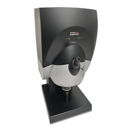
Page 19: Controls And Indicators
Power switch (not visible) Sample viewer Lever to open sample viewer Sample holder Aperture plate (not visible) Status Panel Below is the status panel for the Datacolor ELREPHO: OPTION DESCRIPTION Power Unit is connected to power supply, and power switch is on. Ready Instrument is ready for use. -
Page 20: Powering Up
When the Ready light remains on, your instrument is ready to use. NOTE If the instrument power is not turned on before a Datacolor program is launched, you may receive an error message. Launch a Datacolor program. -
Page 21: Instrument Calibration
When you complete the instrument configuration and select Save Setup, the program prompts you to place the diskette or CD containing the calibration data in the appropriate drive. When you do this, a screen similar to the one below will appear: ELREPHO User's Guide Instrument Calibration • 17... -
Page 22: Reflectance Calibration
The black trap and white tile are used each time the instrument is calibrated. The green tile is used to perform an optional diagnostic test. 18 • Instrument Calibration ELREPHO User's Guide... -
Page 23: Reflectance Calibration Procedure
After these measurements are completed, the program will display a message that the calibration is successful. You can now start measuring samples. The Datacolor Users Guide for the program you are running (e.g., Datacolor Tools, etc.) provides step- by-step instructions regarding the (instrument) software setup and calibration procedure. - Page 24 N O T E S 20 • Instrument Calibration ELREPHO User's Guide...
-
Page 25: Sample Presentation/Measurement
The instrument is also equipped with a sample viewer, referred to as a “peep scope.” By looking through the sample viewer, you can confirm that the sample is properly positioned and completely covers the aperture opening. Sample viewer (peep scope) Sample Holder ELREPHO User's Guide Sample Presentation/Measurement • 21... -
Page 26: Sample Presentation
Before measuring samples, you should use the sample viewing port to check that the sample is properly positioned. To verify that the correct area of the sample is being measured: The sample should be positioned directly against the aperture plate. 22 • Sample Presentation/Measurement ELREPHO User's Guide... -
Page 27: Changing Aperture Plates
Refer to your software documentation for instructions to start the measurement. Changing Aperture Plates The aperture plate is located under the main housing of the instrument. Aperture plate Sample Holder (secured in ‘down’ position) Close-up of aperture plate ELREPHO User's Guide Sample Presentation/Measurement • 23... - Page 28 The user makes this change manually. See the program documentation for instructions to change this software selection. (2) Because of the presence of magnets, keep all magnetic media away from the port opening. 24 • Sample Presentation/Measurement ELREPHO User's Guide...
-
Page 29: Tile Maintenance
• NEVER immerse the tiles in water. • Tiles that have scratches, chips, abrasions or cracks must be replaced. Signs of wear on the tile surface will affect the accuracy of the calibration. ELREPHO User's Guide Tile Maintenance • 25... -
Page 30: Tile Storage
The tiles should always be stored in a protective case or container away from direct sunlight and environmental contaminants. Cleaning the Black Trap • The black trap should be kept dust-free. Dust accumulating in the black trap should be blown out with compressed air. 26 • Tile Maintenance ELREPHO User's Guide... -
Page 31: Appendix
Appendix Optical Block Diagram ELREPHO User's Guide Appendix • 27... -
Page 32: Instrument Specifications
RS232 9600/19200 baud Dimensions English Metric Height 25.0” 635 mm Width 12.3” 312 mm Depth 14.25” 362 mm Weight 42 lbs. 19.05 kg 1 Environmental conditions apply 2 Sample translucency may affect inter-lens agreement 28 • Appendix ELREPHO User's Guide... -
Page 33: Miscellaneous Technical Information
El present appareil numerique n’emet pas de bruits radioelectriques depassant les limites applicables aux appareils numeriques de la class A prescrites dans le Reglement sur le brouillage radioelectrique edicte par le ministere des Communications du Canada. ELREPHO User's Guide Appendix • 29... - Page 34 N O T E S 30 • Appendix ELREPHO User's Guide...
-
Page 35: Index
Dimensions, 28 Powering Up, 16 Effective Bandwidth, 28 Reflectance Electrical Requirements, 3 calibration, 18 Environmental Requirements, 3, 5 calibration procedure, 19 Repeatability, 28 Reporting Interval, 28 RS-232C Connector Pin Assignments, 29 Features Summary, 2 ELREPHO User's Guide Index • 31... - Page 36 Sphere Diameter, 28 USB Cable Installation, 6 Status Panel, 15 Power, 15 filter calibration, 19 Ready, 15 UV Cutoff Filters, 28 System Port Assignment changing, 9 viewing, 9 Wavelength Range, 28 Tile Maintenance, 25 32 • Appendix ELREPHO User's Guide...
Need help?
Do you have a question about the ELREPHO and is the answer not in the manual?
Questions and answers