Table of Contents
Advertisement
Advertisement
Table of Contents

Subscribe to Our Youtube Channel
Related Manuals for Datacolor 800


Summary of Contents for Datacolor 800
- Page 1 Datacolor 800™ Datacolor 500™ Datacolor 850™ Datacolor 550™ User’s Guide...
- Page 2 To obtain information on local agents, contact either of the offices listed below, or visit our website at www.datacolor.com. Support Questions? If you need help with a Datacolor product, please contact one of our top-rated technical support teams listed in the appendix for the Datacolor office in your area.
-
Page 3: Table Of Contents
Exterior Surface Cleaning ................... 33 Sphere Cleaning ......................33 Tile Handling and Cleaning ..................34 Handling Tiles ..................... 34 Cleaning Tiles ..................... 34 Contents i Datacolor 800, 850, 500, and 550 Series User’s Guide... - Page 4 Updating Firmware ....................39 Appendix ......................41 Datacolor 800 Instrument Specifications ................41 Features of the Datacolor 800 and Related Configurations ..........43 Miscellaneous Technical Information ................. 45 System Requirements for USB Connection..............45 ...
-
Page 5: Datacolor Spectrophotometers
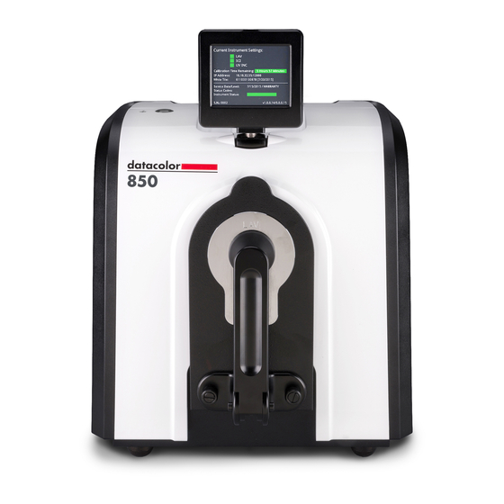
The Datacolor reference-grade benchtop Datacolor 800 spectrophotometer is the newest generation of benchtop color measuring instruments, incorporating an improved integrated circuit technology in the instrument design. The Datacolor 800 is intended for use as a device for measuring, specifying and evaluating color in both laboratory and production settings, especially where precise digital color communication is required. -
Page 6: Electrical/Environmental Requirements
Do not store above 140F (60C) Indoor Use Do not crush, short circuit, mutilate, reverse polarity, disassemble, or dispose. In fire, might cause burns or release toxic materials. Interfaces Serial: RS232 USB: 2.0 Ethernet 4 Datacolor 800, 850, 500, and 550 Series User’s Guide... -
Page 7: Safety Features
Position the product such that the AC power cord that attaches to the rear of the unit is easily accessible and can be disconnected if required. Servicing of this instrument is to be performed only by qualified Datacolor personnel. DO NOT remove bottom cover screws to expose internal components. The following warning is... -
Page 8: Feature Summary
Light source Pulsed xenon Filtered to provide D65 illumination including UV component. Effective 10nm Reliable Spectral data for Bandwidth determining color and color difference. 6 Datacolor 800, 850, 500, and 550 Series User’s Guide... -
Page 9: Accessories
Large Area View (LAV) Medium Area View (MAV) (Optional) Small Area View (SAV) Ultra-Small Area View (USAV) Extra Ultra Small Area View (XUSAV) (Optional) 7 Datacolor 800, 850, 500, and 550 Series User’s Guide... - Page 10 Small (SAV) and ultra-small (USAV) plates should only be used for measurements of samples that do not completely cover the opening of the larger aperture plates. Medium (MAV) with barium coating must be used for transmission measurements. 8 Datacolor 800, 850, 500, and 550 Series User’s Guide...
-
Page 11: Transmittance Options
It has been fitted with a spill tray in the event of minor spillage of liquid samples. Accessing the Transmission Compartment There are side-latch buttons on each side of the Datacolor 850/550 case that are used to open the transmission case: Button Depress these buttons, and slide the case toward the back of the instrument, to open the transmission compartment. -
Page 12: Transmission Accessories
Holder Spill Tray. Installed at factory to catch minor spills. NOTE The cuvette holder is designed to hold an optical glass cuvette 50mm X 10mm (Datacolor Part No. 2950-0004). 10 Datacolor 800, 850, 500, and 550 Series User’s Guide... -
Page 13: Transmission Sample Holders
Loosen the thumbscrews on the solid sample holder to aid in the installation of the sample holder. Make sure the sphere opening/lens opening is completely covered by the sample you are going to measure. No special tools are required to install the sample holders. 11 Datacolor 800, 850, 500, and 550 Series User’s Guide... - Page 14 The location of the sample holder along the base depends upon the type of material being measured. NOTES The base should remain in the transmission compartment, but the sample holders (Solid or Cuvette) must be removed for Reflectance calibration and measurement. 12 Datacolor 800, 850, 500, and 550 Series User’s Guide...
-
Page 15: Cable Installation
USB cable. Select one of them. This section provides instructions for using the serial cable. NOTE Do not connect all interface cables to the unit at the same time. 13 Datacolor 800, 850, 500, and 550 Series User’s Guide... - Page 16 You may need to enter this information into the program. 4. Tighten each connection securely to ensure proper signal. See the Appendix for a description of the RS-232C connector pin assignments. 14 Datacolor 800, 850, 500, and 550 Series User’s Guide...
-
Page 17: Usb Cable Installation
USB Cable Installation Instruments manufactured by Datacolor can be connected to a USB port on a desktop system. See Appendix, System Requirements for USB Connection before you attempt to connect to a USB port. You can connect the instrument to the computer using either a serial cable, Ethernet cable, or a USB cable. -
Page 18: Driver Installation
Driver Installation All current Datacolor software ships with the necessary drivers for the Datacolor 800. If you are using Third party software with the Datacolor 800, please contact Datacolor Support via our website at: http://industrial.datacolor.com/industrial-support/ Viewing/Changing System Port Assignment As part of the USB driver installation, a COM port number is assigned to the USB port. The default selection is the next available COM port. -
Page 19: Ethernet Cable Installation
Ethernet Cable Installation Instruments manufactured by Datacolor can now be connected to an Ethernet port on a desktop system. See Appendix, Ethernet Connection Considerations, before you attempt to connect to an Ethernet port. You can connect the instrument to the computer using either a serial cable, Ethernet cable, or a USB cable. -
Page 20: Controls And Indicators
Depending on the model, the LCD Status Display can be raised and rotated to the left or right. Do not rotate the LCD more than 45 degrees to the left or right while the LCD is raised. 18 Datacolor 800, 850, 500, and 550 Series User’s Guide... -
Page 21: Powering Up
Status Display is shown. NOTE If the instrument power is not turned on before a Datacolor program is launched, you may receive an error message. 4. Depending on the model you are using, the LCD Display may include the status of the following mechanisms: ... - Page 22 N O T E S 20 Datacolor 800, 850, 500, and 550 Series User’s Guide...
-
Page 23: Instrument Calibration
White Calibration Tiles be replaced annually. If you need to replace your White Calibration Tile, please contact your local Datacolor office. Upon receipt of a new tile, calibration data can be found on the USB Memory Stick or CD included with the tile. Install the data directly on the instrument by inserting a USB Memory Stick containing the WHITESE.DAT and... - Page 24 WHITESE.DAT and WHITESI.DAT files on the USB stick, corresponding to the new White Calibration Tile. The instrument will automatically be restarted after the update. The LCD Status Display will reflect the serial number of the new tile. 22 Datacolor 800, 850, 500, and 550 Series User’s Guide...
-
Page 25: Reflectance Calibration
5. After these measurements are completed, the program will display a message that the calibration is successful. You can now start measuring samples. The Datacolor User’s Guide for the program you are running (e.g., Datacolor TOOLS, etc.) provides step-by-step instructions regarding the (instrument) software setup and calibration procedure. -
Page 26: Uv Filter Calibration
Standard) that may be used as a reference standard after the instrument has been calibrated for UV using an official UV calibration standard. An applicable whiteness value can only be assigned to the Datacolor Fluorescent Reference Standard after the instrument has been calibrated for UV using an official UV calibration standard. This procedure requires the selection of specific software options. -
Page 27: Transmittance Calibration
(transmission). See also the User’s Guide for the program you are running for detailed instructions to access the instrument setup and calibration options. 25 Datacolor 800, 850, 500, and 550 Series User’s Guide... - Page 28 The white Spectralon® plaque remains at the port for “Regular” and “Total” Transmittance measurements, and is replaced with the black trap for “Diffuse” Transmittance measurements. See also Transmittance Measurements 26 Datacolor 800, 850, 500, and 550 Series User’s Guide...
-
Page 29: Sample Presentation And Measurement
3. The backside of this door reveals the area of the sample covering the port opening. If necessary, adjust the placement of the sample to target the portion of the sample to be measured. 4. Push the door back to its normal position. 27 Datacolor 800, 850, 500, and 550 Series User’s Guide... -
Page 30: Sample Viewing Display
Sample Viewing Display When measuring samples on the Datacolor 800, 800V, and 850, the status display also serves as a display for sample placement. Toggle to the sample camera view on the LCD by pressing and holding the Remote Measure Button for approximately one second. -
Page 31: Transmittance Measurements
“regular” transmittance. These samples need to be positioned close to the lens opening at the back of the transmission compartment using either the cuvette holder or solid sample holder as appropriate: Regular Transmittance 29 Datacolor 800, 850, 500, and 550 Series User’s Guide... -
Page 32: Total, Diffuse, And Haze Transmittance
Use the solid sample holder to place the solid sample flush against the sphere opening. In order to ensure the best measurement, there must be no gap between the sample and the sphere opening in “Total”, “Diffuse”, or Haze measurements. 30 Datacolor 800, 850, 500, and 550 Series User’s Guide... - Page 33 Total Transmittance Diffuse Transmittance Consult with your Applications Specialist regarding the measurement technique you should use for specific evaluations. 31 Datacolor 800, 850, 500, and 550 Series User’s Guide...
- Page 34 N O T E S 32 Datacolor 800, 850, 500, and 550 Series User’s Guide...
-
Page 35: Maintenance
Datacolor strongly recommends that the instrument be serviced once/year by an authorized service engineer. Datacolor offers a variety of maintenance and certification services to match your needs. Please contact your local Datacolor office for more information. The sections that follow provide detailed instructions for maintaining the instrument and calibration tiles. -
Page 36: Tile Handling And Cleaning
Prolonged exposure to sunlight or other sources of ultra-violet radiation will cause the color of the tiles to change. The tiles should always be stored in a protective case or container away from direct sunlight and environmental contaminants. 34 Datacolor 800, 850, 500, and 550 Series User’s Guide... -
Page 37: Cleaning The Black Trap
1. Sand the surface under running water with a 220 – 240 grit waterproof emery cloth, until the surface is totally hydrophobic (water beads and runs off immediately). 2. Blow dry with clean air or nitrogen, or allow the material to air dry. 35 Datacolor 800, 850, 500, and 550 Series User’s Guide... -
Page 38: Handling And Cleaning The Cuvette
The cuvette is made of optical glass. It is recommended that standard methods applicable to the cleaning of optical glass cuvettes be used as required between the measurements of different samples. 36 Datacolor 800, 850, 500, and 550 Series User’s Guide... -
Page 39: Instrument Status
Instrument Status bar to be yellow or red in color. Corresponding Status Codes will also be displayed. Should these conditions occur, please contact your local Datacolor office for more information and guidance regarding next steps. -
Page 40: Exporting Diagnostic Data
Exporting Diagnostic Data Diagnostic data is stored on the instrument. Your local Datacolor office may ask for this data in order to remotely service your instrument. This data can be retrieved via a USB Memory Stick. 1. Upon inserting a USB Memory Stick into the instrument, you will see a screen... -
Page 41: Updating Firmware
4. The data will be stored in a folder named with the following pattern: “Backup”- <InstrumentModel>-<InstrumentSerialNumber>-<CurrentDateTime> Updating Firmware The instrument’s firmware can also be updated via a USB Memory Stick. Please contact your local Datacolor office before attempting to update the instrument’s firmware. 39 Datacolor 800, 850, 500, and 550 Series User’s Guide... - Page 42 N O T E S 40 Datacolor 800, 850, 500, and 550 Series User’s Guide...
-
Page 43: Appendix
In fire, might cause burns or release toxic materials. Interface Serial: RS232 USB: 2.0 Ethernet 3.5" RGB Color Display Module Max Resolution 320 x 240 Maximum Pixel Clock 28 MHz 41 Datacolor 800, 850, 500, and 550 Series User’s Guide... - Page 44 H 13.2” x W 12.3” (33.53 cm x 31.24cm) Weight: 37.5 lbs (17.01kg) * Sample translucency may affect inter-lens agreement ** Dimensions shown are for horizontal mount instruments. 42 Datacolor 800, 850, 500, and 550 Series User’s Guide...
-
Page 45: Features Of The Datacolor 800 And Related Configurations
550 ±0.10% at ±0.20% at 32% T 32% T Inter-instrument — — ±0.15% at — — ±0.30% at agreement – 10% TH 10% TH transmission haze measurements 43 Datacolor 800, 850, 500, and 550 Series User’s Guide... - Page 46 Transmission — — 22 mm — — 22 mm aperture size * Measurements made at 23º C +/- 1º C. 44 Datacolor 800, 850, 500, and 550 Series User’s Guide...
-
Page 47: Miscellaneous Technical Information
Miscellaneous Technical Information System Requirements for USB Connection Below are the software and firmware versions required to successfully connect a Datacolor instrument to a USB port. Operating Systems Windows 7 or higher USB Firmware 2.0 or higher Ethernet Connection Considerations The instrument connects to an Ethernet port via a standard Cat 5 cable. -
Page 48: Datacolor Global Support
Datacolor Global Support A complete User’s Guide is provided with this product. However there are also resources regarding color education on the Datacolor website, including contact information for local Datacolor offices. http://industrial.datacolor.com/support/contact-us-2/ 46 Datacolor 800, 850, 500, and 550 Series User’s Guide...
Need help?
Do you have a question about the 800 and is the answer not in the manual?
Questions and answers