
Subscribe to Our Youtube Channel
Related Manuals for ADDAC System ADDAC713


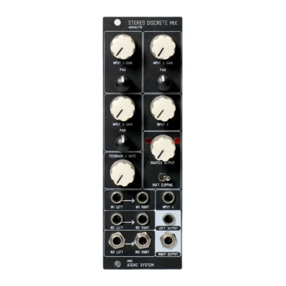
Summary of Contents for ADDAC System ADDAC713
- Page 2 ADDAC713 Assembly Guide February.2023 ADDAC SYSTEM page 2...
- Page 3 ADDAC713 Assembly Guide STEP 1: Grab the pcb, gently brake it apart and trim the excess with a cutting plier. STEP 2: Locate all TO-92 parts and sepa- rate them as shown here. Notice the orientation of the part printed on the pcb and place them in their respective places.
- Page 4 ADDAC713 Assembly Guide STEP 3: Next place and solder the trimmers as shown, the golden dials should be facing outwards. STEP 4: Place and solder the 2x8 pinheader. STEP 5: Place and solder the 2x5 boxed pinheader. Notice the indent orientation.
- Page 5 ADDAC713 Assembly Guide ! NOTICE ! These steps are only necessary for the pcbs that have the jumpers on the back, in newer revisions these jumpers were removed. STEP A: Place and solder the jumpers on the back of the pcb.
- Page 6 ADDAC713 Assembly Guide STEP 7: Next attach the spacers as shown. STEP 8: Grab both pcbs allign them together and solder the pinheaders on the top pcb. ADDAC SYSTEM page 6...
- Page 7 ADDAC713 Assembly Guide STEP 9: Next we’ll need to prepare some parts before placing them to the front panel. Locate all trim pots and flatten out their legs with the help of some pliers, like shown below. STEP 10: Locate the jacks and cut the thinest leg like shown below.
- Page 8 ADDAC713 Assembly Guide STEP 11: Next place all parts on the pcb, notice the values, orientation and jack types like shown below. B10k = 103 B10k = 103 (6 LEGS) (6 LEGS) B10k = 103 B10k = 103 (TRIM POT)
- Page 9 ADDAC713 Assembly Guide STEP 12: Place the frontpanel and tighten all nuts. ADDAC SYSTEM page 9...
- Page 10 ADDAC713 Assembly Guide STEP 13: Adjust the height of the pcb keeping it parallel to the front panel and proceed to solder all parts. Keep lines parallel STEP 14: Place the 2 back screws. ADDAC SYSTEM page 10...
- Page 11 ADDAC713 Assembly Guide Finish it by placing the knobs and you’ve finished the assembly process! Proceed to the calibration method. ADDAC SYSTEM page 11...
- Page 12 ADDAC713 Assembly Guide Calibration TRIMMER LOCATIONS TUNING THE BIAS: An oscilloscope is required to precisely adjust the bias. 1. Start by turning all Inputs and the Feedback/Gate knobs fully counter-clockwise and set the MASTER OUTPUT at 12 o’clock. 2. Plug a Triangle waveform into INPUT 1 LEFT and connect the LEFT OUTPUT to the oscilloscope.
-
Page 13: Assembly Guide
For feedback, comments or problems please contact us at: addac@addacsystem.com ADDAC713 ASSEMBLY GUIDE Revision.01 February.2023...
Need help?
Do you have a question about the ADDAC713 and is the answer not in the manual?
Questions and answers