
Related Manuals for ADDAC System STEREO MIXER+ ADDAC813


Summary of Contents for ADDAC System STEREO MIXER+ ADDAC813
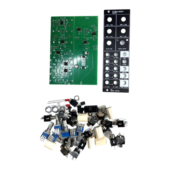
- Page 2 ADDAC813 Assembly Guide May.2024 ADDAC SYSTEM page 2...
- Page 3 ADDAC813 Assembly Guide STEP 1: Start by grabbing the pcb and gently brake it apart. STEP 2: Locate the plastic screw and attach it to the spacer like shown below. ADDAC SYSTEM page 3...
- Page 4 ADDAC813 Assembly Guide STEP 3: Next let’s place all pinheaders. STEP 4: Proceed by placing the back screw to hold the pinheaders in place and solder them to both pcbs ADDAC SYSTEM page 4...
- Page 5 ADDAC813 Assembly Guide STEP 5: Next place and solder the remaining pinheader and boxed header .Notice the orientation of the boxed header. STEP 6: Locate the jacks and cut the thinest leg like shown below. ADDAC SYSTEM page 5...
- Page 6 Notice all parts’ details below, make sure the panel is parallel to the pcb, it’s recommended to slightly raise the potentiometers from the pcb to get the best result. DUAL A10k DUAL A10k DUAL A10k DUAL A10k B10k = 103 DUAL A10k Non-threaded Jacks Threaded Jacks ADDAC SYSTEM page 6...
- Page 7 ADDAC813 Assembly Guide STEP 8: Next place the bottom screw and the jumper at the setting of your liking. ADDAC SYSTEM page 7...
- Page 8 ADDAC813 Assembly Guide Complete it by placing the knobs and you’ve finished the assembly process! Happy patching! ADDAC SYSTEM page 8...
-
Page 9: Assembly Guide
For feedback, comments or problems please contact us at: addac@addacsystem.com ADDAC813 ASSEMBLY GUIDE Revision.01 May.2024...
Need help?
Do you have a question about the STEREO MIXER+ ADDAC813 and is the answer not in the manual?
Questions and answers