Advertisement
- 1 GENERAL SPECIFICATIONS
- 2 DEVICE AND EQUIPMENTS
- 3 TECHNICAL DATA
- 4 ROOM THERMOSTAT
- 5 RECEIVER
- 6 ROOM THERMOSTAT PLACEMENT
- 7 BATTERY PLACEMENT
- 8 RECEIVER PLACEMENT
- 9 RECEIVER SETUP
- 10 RECEIVER WIRING DIAGRAM
- 11 PAIRING THE ROOM THERMOSTAT AND THE RECEIVER
- 12 ROOM THERMOSTAT TEMPERATURE CALIBRATION
- 13 ROOM THERMOSTAT HEATING / COOLING MODES
- 14 ROOM THERMOSTAT HYSTERESIS POSITIVE MENU
- 15 ROOM THERMOSTAT HYSTERESIS NEGATIVE MENU
- 16 FACTORY SETTINGS RESET
- 17 ROOM THERMOSTAT WORKING LOGIC
- 18 FREQUENTLY ASKED QUESTIONS
- 19 DECLARATION OF CONFORMITY
- 20 WARRANTY CONDITIONS
- 21 WARRANTY CERTIFICATE
- 22 Documents / Resources
GENERAL SPECIFICATIONS
MITRA 220 RF is a wireless room thermostat. The user can adjust the room temperature with the required temperature and get more comfortable and economic heating/cooling.
- Precise Temperature Measurement
- Heating calibration
- Heating/Cooling Modes
- ON/OFF Control
- Wireless Connection
- Hysteresis Settings
DEVICE AND EQUIPMENTS

TECHNICAL DATA
Room Thermostat
| Dimensions | 85mm / 125mm / 24mm |
| Operating Current | 3V DC (2 x AAA alkaline battery) |
| Temperature Measurement Accuracy | 0.1oC |
| Operating Sensitivity | (-2.0oC) – (+2.0oC) |
| Operating Temperature Range | (5oC) – (30oC) |
| Battery Life | 1 Years (2 x AAA) |
| Operating Temperature | (-10oC) – (+50oC) |
| Storage Temperature | (-20oC) – (+60oC) |
Receiver
| Dimensions | 90mm / 90mm / 25mm |
| Operation Current | 230V AC |
| Relay NO Switching Current | 7A (240VAC – Resistive load) 10A (120VAC – Resistive load) |
| Storage Temperature | (-20oC) – (+60oC) |
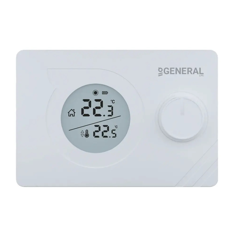
ROOM THERMOSTAT

| 1 |  | Battery Indicator |
| 2 |  | Heating Indicator
|
| 3 |  | Cooling Indicator
|
| 4 |  | Room Temperature |
| 5 |  | Set Temperature |
| 6 | ON/OFF and Temperature Setting Button |
RECEIVER

- Manual Operation Button:
Deactivates the Receiver and allows you to use heating/cooling unit manually. - Pairing Button:
Pairs the Receiver and the Room Thermostat. - Receiver LED Light
- Receiver Power Cable Input
- Heating/Cooling Unit Connection Cable Input
RECEIVER LED DESCRIPTIONS
| Constant Red | Receiver has power but Receiver and Room Thermostat are not paired. |
| Blinking Green | Waiting for pairing signal from the Room Thermostat. |
| Constant Green | Receiver and Room Thermostat are paired. Heating/cooling unit is not operating. |
| 3 Short Orange Blinking | Operate the heating/cooling unit signal has reached to the Receiver. |
| Constant Orange | Heating/cooling unit is operating. |
| 3 Short Green Blinking | Shut the heating/cooling unit down signal has reached to the Receiver. |
| Blinking Orange | Heating/Cooling unit operates in manual mode. |
| Blinking Red | Receiver did not get any signal from the Room Thermostat for 22 minutes or longer. Heating/cooling unit has shut down. |
ROOM THERMOSTAT PLACEMENT
Room Thermostat needs to be placed in the room which is used most frequently. For instance; living room or lounge. Placing the Room Thermostat in a spot that have air circulation like entrance of a room or side of window should be avoided. Also anywhere close to heating/cooling units such as radiator, stove and spots which get direct sun lights would not be suitable. Room Thermostat needs to be located above the floor 150 cm height. Few trials may be made to find the most convenient spot.


BATTERY PLACEMENT

As shown in the picture above, press the screwdriver forward from the space shown, bend the tabs and separate the front cover. Insert 2 new AAA alkaline batteries in the battery housing with the correct battery direction. Replace both batteries at the same time. Then align the front part of your Room Thermostat to the back and squeeze it towards the back.
Low Battery Warning: When the "  " icon appears on the screen, it means "low battery warning". It is recommended to replace the batteries when this warning appears.

When the product is not used for a long period (more than 15 days), remove the batteries. Otherwise, malfunctions that may occur would be out of warranty.
Please throw your dead batteries into the waste bin for batteries.
RECEIVER PLACEMENT
The important things to note for the Receiver placement is avoiding physical contact between the Receiver and heating/cooling unit, and protecting it against materials such as liquid, dust etc.

The devices should be placed in order to minimize the damage to the received and transmitted signals by paying attention to the following points;
- The devices should not be mounted on metal surfaces.
- The devices should not be installed close to electrical cables and electronic equipment such as computers and television units.
- The devices should not be installed near large metal structures or other building materials using fine metal meshes such as special glass or special concrete.
- Distance between the Room Thermostat and the Receiver should not exceed 20 meters or 2 floors.
- Receiver must be installed at least 50 cm away from the heating/cooling unit.
RECEIVER SETUP
- First, shut down your heating/cooling unit and your heating/cooling unit's power source with all electrical current (fuse, socket etc.)
- As shown in the connection diagram, connect one end of the heating/cooling unit connection cable to the COM and the other to the NO input of the Receiver.
- Connect the other ends of the cable -which you connected to the Receiver to room thermostat connection terminal as shown in your heating/cooling unit's user manual.
- You must first connect the Receiver power cable to the Receiver and then to the fuse to which the heating/cooling unit is connected.
- After completing the cable connection process, firstly turn on your fuse and then your heating/cooling unit.
- By pressing the Receiver's manual usage button for 2 seconds, you should see the Orange Light blinking on the Receiver. In this way, after making sure that the heating/cooling unit is operating, press the same button again for 2 seconds and see that the Orange LED turns off.
- Set up the Room Thermostat to pair the Receiver with the Room Thermostat.
RECEIVER WIRING DIAGRAM

Operations within the heating / cooling unit or the electrical installation must be carried out by professionally qualified persons.
PAIRING THE ROOM THERMOSTAT AND THE RECEIVER
- Primarily press the sync button of receiver for 2 seconds and see blinking green light of receiver.
- While your device is turned off, press and hold the button for 3 seconds.
- Press the button until the "
![]() " menu appears.
" menu appears. - Then turn up the button to right or left way.
- If the pairing is successful, the green flashing LED on the receiver will be constant.
- Receiver and Room Thermostat have been paired to each other.
 " menu appears.
ROOM THERMOSTAT TEMPERATURE CALIBRATION
Temperature sensors which are used in Room Thermostats are highly sensitive. You may need to calibrate your Room Thermostat if you would like to get the same temperature values with other thermometers in your living space.
- While your device is turned off, press and hold the button for 3 seconds.
- Press the button until the "
![]() " menu appers. In order to see the desired temperature, set the temperature difference by turning the button to right or left. This value can be arranged between "-8oC" and "+8oC".
" menu appers. In order to see the desired temperature, set the temperature difference by turning the button to right or left. This value can be arranged between "-8oC" and "+8oC". - To save the settings and exit, press the "On/Off" button until the device turns off.
 " menu appers. In order to see the desired temperature, set the temperature difference by turning the button to right or left. This value can be arranged between "-8oC" and "+8oC".
Note: Recommended tempreture calibration is "0.0oC".
ROOM THERMOSTAT HEATING / COOLING MODES
Your Room Thermostat has heating and cooling modes. In order to switch easily between heating and cooling modes:
- While your device is turned off, press and hold the button for 3 seconds.
- Press the button until the "
![]() " menu appears.
" menu appears. - You can switch between "
![]() " (heating) and "
" (heating) and " ![]() " (cooling) modes by turning the button to right or left in the "
" (cooling) modes by turning the button to right or left in the " ![]() " menu.
" menu. - To save the settings and exit, press the button until the device turns off.
- The settings you have made have been saved. Once you turned on your device, it will operate with the changed settings.
 " menu appears.
 " (heating) and "
  " (cooling) modes by turning the button to right or left in the "
  " menu.
ROOM THERMOSTAT HYSTERESIS POSITIVE MENU
Hysteresis positive factory setting of your room thermostat is 0.5°C. This value may be adjusted between "0.1°C" and "2.0°C". While hysteresis positive value is 0.5°C, if the room temperature goes above 0.5°C of set temperature, your room thermostat will send a signal to your heating/cooling unit.
For instance, when you set your room thermostat to 22.0°C, if the room temperature goes above 22.5°C, on heating mode your heating unit will stop working; on cooling mode your cooling unit will start working. In order to change the hysteresis positive setting:
- Press the button for 3 seconds while your device is off.
- Press the button until "
![]() " menu appears.
" menu appears. - Adjust the operating sensitivity by turning the button to the left or right in the "
![]() " hysteresis positive menu.
" hysteresis positive menu. - Press the button until device turns off to save the changes and exit.
- Changes have been saved. Your room thermostat will be working with set operating sensitivity when you open your device.
 " menu appears.
 " hysteresis positive menu.
ROOM THERMOSTAT HYSTERESIS NEGATIVE MENU
Hysteresis negative factory setting of your room thermostat is -0.5°C. This value may be adjusted between "-0.1°C" and "-2.0°C". While hysteresis negative value is -0.5°C, if the room temperature goes below 0.5°C of set temperature, your room thermostat will send a signal to your heating/cooling unit.
For instance, when you set your room thermostat to 22°C, if the room temperature goes below 21.5°C, on heating mode your heating unit will start working; on cooling mode your cooling unit will stop working. In order to change the hysteresis negative setting:
- Press the button for 3 seconds while your device is off.
- Press the button until "
![]() " menu appears.
" menu appears. - Adjust the operating sensitivity by turning the button to the left or right in the "
![]() " hysteresis negative menu.
" hysteresis negative menu. - Press the button until device turns off to save the changes and exit.
- Changes have been saved. Your room thermostat will be working with the set operating sensitivity when you open your device.
 " menu appears.
 " hysteresis negative menu.
FACTORY SETTINGS RESET
You can reset your Room Thermostat to its default factory settings. This operation resets the calibration setting, heating/coling modes and hysteresis settings to factory setting. To reset your Room Thermostat to factory setting:
- While your device is turned off, press and hold the button for 3 seconds.
- Press the button until the "
![]() " menu appears.
" menu appears. - While in the "
![]() " menu, turn the button to right or left in order to select "
" menu, turn the button to right or left in order to select " ![]() " option and press the button.
" option and press the button. - Your device will be turned off and reset to factory settings.
 " menu appears.
 " menu, turn the button to right or left in order to select "
  " option and press the button.
ROOM THERMOSTAT WORKING LOGIC
Heating Mode
Your room thermostat takes the average room temperature of last 40 seconds as basis. If the room temperature goes above the hysteresis positive temperature value you set, your Room Thermostat will stop the heating unit. If it goes below the hysteresis negative temperature value, your Room Thermostat will start the heating unit. Thus, it ensures that the room temperature remains within a certain range.

Cooling Mode
Your Room Thermostat takes the average room temperature of last 40 seconds as basis. If the room temperature goes above the hysteresis positive temperature value you set, your Room Thermostat will start the cooling unit. If it goes below the hysteresis negative temperature value, your Room Thermostat will stop the cooling unit. Thus, it ensures that the room temperature remains within a certain range.

Your Room Thermostat sends the last status signal to the Receiver every 10 minutes. Thus, your Room Thermostat and Receiver work synchronously. If the signal cannot reach to the Receiver from the Room Thermostat for 22 minutes, it perceives that the connection is broken and stops the heating/cooling operation for safety reasons. Likewise, in cases where the electricity comes back after a power failure, the Receiver do not operate the heating/cooling unit until 'operate' signal reaches from the Room Thermostat.
However, in this case, if the Room Thermostat continues to operate normally, it will continue to work properly without any need for intervention since it sends a status signal to the Receiver every 10 minutes.
FREQUENTLY ASKED QUESTIONS
- Is my Room Thermostat compatible with my heating/cooling unit?
If your heating / cooling unit has on-off connections, your Room Thermostat is compatible. You can find information about your heating / cooling unit from your heating / cooling unit operating manual or from your heating / cooling unit service.
- How will I connect my heating/cooling unit with my Receiver?
We recommend that the connection between the Receiver and heating/cooling unit should be made by professionally qualified persons. 2x0.75 mm cable is sufficient for the Receiver – heating/cooling unit connection.
Connect one end of the cable pair to the room thermostat connection terminals stated in the user manual of your heating/cooling unit.
Connect the other end of the cable pair to COM and NO inputs of the terminal inside the Receiver as shown in the "RECEIVER WIRING DIAGRAM" section.
The direction of the cable ends does not matter.
DECLARATION OF CONFORMITY
ISIPARK İÇ VE DIŞ TİC. İNŞ. ISITMA SİSTEMLERİ OTO. SAN.A.Ş.which Head Office and production site is located on Fatih Mah. 1188 Sk. No: 13/A Sarnıç - Gaziemir - İZMİR – TÜRKİYE confirms and declares that the product marked with CE and its specifications below is covered by the provisions of the mentioned directive.
Brand: GENERAL Life
Product Name: MITRA 220 RF
Product Type: Digital Room Thermostat Compatible Directives:
Radio and Telecommunications Terminal Equipment Regulation
2014/53/EU (R&TTE/RED EN 301 489-1 V2.1.1:2017,
EN 300 220-1 V3.1.1:2017, EN 301 489-3 V2.1.1:2017, EN 300 220-2 V3.1.1:2017, EN 62479: 2010)
Electromagnetic Compatibility Regulation 2014/30/EU
(EMC EN 61000-6-3: 2007 + A1: 2011, EN 61000-6-1: 2007) Low Voltage Directive 2014/35/EU
(LVD EN 60730-2-9:2010, EN 60730-1:2011)
Additional Information: The mentioned product can be used with heating/cooling units with on / off output and compliance with the directives only covers the product. ISIPARK is not responsible for the entire system's compliance with the directives. This statement is not valid if changes are made to the product without our approval.
WARRANTY CONDITIONS
- The warranty period starts from the invoice date and warranted against manufacturing defects for 5 years.
- Devices and apparatus are delivered to the customer in working condition in our company. On-site commissioning is subject to a service fee.
- In case of detection of manufacturer-induced errors of devices and apparatus whose warranty period continues, the customer can request a replacement or repair of the devices and apparatus at full expense by the manufacturer, unless it's higher than the product's price.
- The warranty document must be kept by the customer during the warranty period. If the document is lost, a second document will not be issued. In case of loss, repair and replacement of devices and apparatus will be made for a fee.
WARRANTY CERTIFICATE
Manufacturer
Title: ISIPARK İÇ DIŞ TİC. A.Ş.
Adress: Fatih Mah. 1188 Sk. No: 13/A Sarnıç Gaziemir İzmir-TÜRKİYE
Tel: +90 (232) 457 99 50
Fax: +90 (232) 457 91 22
E-mail: generallife@generallife.com.tr
Authorized Signature: Company Stamp:
Product
Type: Digital Room Thermostat
Brand: GENERAL Life
Model: MITRA 220 RF
Warranty Period: 5 Years
Max. Time to Repair: 20 Days
Bandrol and Serial Number:
ISIPARK reserves the rights of changing product specifications and user manuals.
* For all changes, you may visit generallife.com.tr

Documents / Resources
References

Download manual
Here you can download full pdf version of manual, it may contain additional safety instructions, warranty information, FCC rules, etc.
Download GENERAL LIFE MITRA 220 RF - Digital Room Thermostat Manual
Advertisement


Need help?
Do you have a question about the MITRA 220 RF and is the answer not in the manual?
Questions and answers