Advertisement
Quick Links
HARDWARE LISTS AND TOOLS REQUIRED
Item
M6 x 8
6X14 Bolt
(Wood Top)
5x16 Screw
(Wood Top)
M8x37
(Foots)
Connect Bar -
1. 24"D Top (Short)
2. 30"D Top (Long)
Crank Box
Pull Holder
Pull Handle
Leveler
Last Updated: 3/2023
®
®
ASSEMBLY INSTRUCTIONS
ASSEMBLY INSTRUCTIONS
Number
Drawing
A
B
C
D
E
F
G
H
I
®
®
ASSEMBLY INSTRUCTIONS
MODEL NO. PLTCRKB36WF30
PLTCRKB60WF30
PLTCRKB36WF30
QTY
Tool
16 PCS
4mm Allen Wrench
4 PCS
Cross-Head screw driver
16 PCS
Cross-Head screw driver
8 PCS
5mm Allen Wrench
2 PCS
N/A
1 PCS
N/A
1 PCS
N/A
1 PCS
N/A
4 PCS
N/A
www.officesourcefurniture.com
www.officesourcefurniture.com
OFFICESOURCE.COM
Advertisement

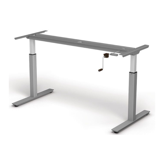
Summary of Contents for OfficeSource PLTCRKB36WF30
- Page 1 ASSEMBLY INSTRUCTIONS MODEL NO. PLTCRKB36WF30 ® ® PLTCRKB60WF30 PLTCRKB36WF30 ASSEMBLY INSTRUCTIONS ASSEMBLY INSTRUCTIONS HARDWARE LISTS AND TOOLS REQUIRED Item Number Drawing Tool M6 x 8 16 PCS 4mm Allen Wrench 6X14 Bolt 4 PCS Cross-Head screw driver (Wood Top) 5x16 Screw...
-
Page 2: Installation Instruction
ASSEMBLY INSTRUCTIONS ® PLTCRKB60WF30 ASSEMBLY INSTRUCTIONS MODEL NO. PLTCRKB36WF30 ® PLTCRKB36WF30 ASSEMBLY INSTRUCTIONS INSTALLATION INSTRUCTION Step 1 Take both leg and the middle support out of the box , attach both legs to the main frame Step 2 Attach both legs to the frame Important: Make sure the red dots are on the same side ®... - Page 3 ASSEMBLY INSTRUCTIONS ® MODEL NO. PLTCRKB36WF30 PLTCRKB60WF30 ASSEMBLY INSTRUCTIONS ® PLTCRKB36WF30 ASSEMBLY INSTRUCTIONS Step 3 install (Screw A, 12 PCS) on both legs Tools Step 4 Install the side frame to the main frame with ( Screw A , 4 PCS ) Tools ®...
- Page 4 ASSEMBLY INSTRUCTIONS MODEL NO. PLTCRKB36WF30 ® PLTCRKB60WF30 ® ASSEMBLY INSTRUCTIONS PLTCRKB36WF30 ASSEMBLY INSTRUCTIONS Step 5 Flip over the table base and put it on the back of the wood top Step 6 Install (Screw B, 4 PCS) and (Screw C , 10 PCS)
- Page 5 ASSEMBLY INSTRUCTIONS MODEL NO. PLTCRKB36WF30 ® PLTCRKB60WF30 ASSEMBLY INSTRUCTIONS ® PLTCRKB36WF30 ASSEMBLY INSTRUCTIONS Step 8 Install the Pull Holder (Part H) using (Screw C, 2 PCS) Tools Step 9 Install the feet with (Screw D, 8 PCS), then install the glides (Part I, 4 PCS) Tools ®...
- Page 6 ASSEMBLY INSTRUCTIONS MODEL NO. PLTCRKB36WF30 ® PLTCRKB36WF30 ASSEMBLY INSTRUCTIONS ® PLTCRKB60WF30 ASSEMBLY INSTRUCTIONS Step 10 Flip over the table ® www.officesourcefurniture.com OFFICESOURCE.COM Last Updated: 3/2023...


Need help?
Do you have a question about the PLTCRKB36WF30 and is the answer not in the manual?
Questions and answers