
Subscribe to Our Youtube Channel
Related Manuals for JAI TM-2016-8


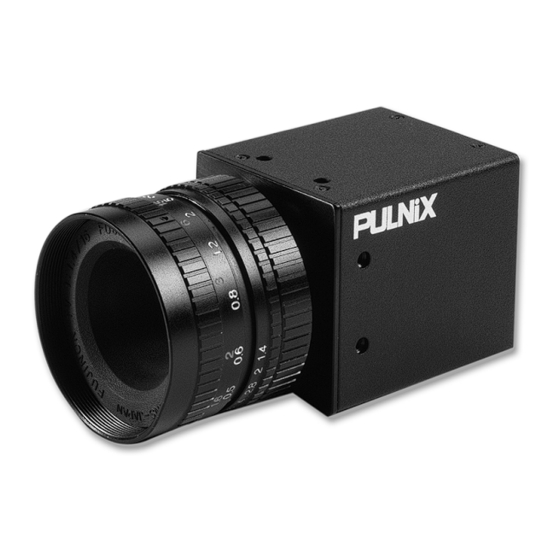
Summary of Contents for JAI TM-2016-8
- Page 1 TM-2016-8/8CL Progressive Scan Shutter Cameras O p e r a t i o n M a n u a l 69-0093 Rev. B...
- Page 2 Page ii...
- Page 3 Notice The material contained in this manual consists of information that is proprietary to JAI, Inc., and may only be used by the pur- chasers of the product. JAI, Inc. makes no warranty for the use of its product and assumes no responsibility for any errors which may appear or for damages resulting from the use of the information contained herein.
- Page 4 Page iv WARNING Changes or modifications to this unit not expressly approved by the party responsible for FCC compliance could void the user’s authority to operate the equipment. TM-2016-8/8CL Operation Manual JAI, Inc. 625 River Oaks Parkway San Jose, CA 95134...
-
Page 5: Table Of Contents
..... .10 2.2.4 RS-232 Communication Cable (TM-2016-8 only) ....10 2.2.5 Digital Output Cable (TM-2016-8 only) -
Page 6: Table Of Contents
........26 3.11 Serial Communication Kit (TM-2016-8) . -
Page 7: List Of Figures
FIGURE 1. TM-2016-8 System Configuration ....... . 4 FIGURE 2. - Page 8 Page viii List of Figures...
-
Page 9: List Of Tables
........16 TABLE 7. TM-2016-8 and TM-2016-8CL Product Specifications Table ..29... - Page 10 Page x List of Tables...
-
Page 11: Introduction
The frame rate is 8 fps. The TM-2016-8 has a full dynamic range control function, which can be set at externally selectable look-up table (LUT) knee slopes to convert 10-bit input to 8-bit output, thereby optimizing the CCD’s full dynamic range in the normal output signal range. -
Page 12: Features
• Miniaturized and lightweight The printed circuit boards in the TM-2016-8 have been arranged based on a new design philosophy that creates modular electronics for the camera, giving it flexibility. In addition, the use of miniature solid-state components results in a compact, lightweight camera that is 44mm x 44mm x 64mm in dimensions, and weighs only 136 grams (CL version 141 grams). -
Page 13: Functional Options
1.3 Functional Options • Adjustable back-focus front end. • Pixel clock locking *. Pixel clock locking not available at time of publishing. Please check with JAI, Inc. for current availability. Introduction... -
Page 14: System Configuration
Page 4 TM-2016-8 and TM-2016-8CL Progressive Scan Shutter Camera 1.4 System Configuration TM-2016-8 System Configuration FIGURE 1. Figure 1 below presents a typical system configuration for the TM-2016-8 camera. DOWN SHUTTER MODE Digital cable DIGITAL RS-232B-12 cable in VIDEO POWER... -
Page 15: Installation
2.2.1 Heat Dissipation The TM-2016-8 camera from JAI, Inc., is a compact 2K by 1K camera. Since all the electronics have been packed in a compact package, the outer case of the camera gets hot due to heat dissipation. For optimal performance, JAI, Inc. -
Page 16: Connector Pin Configurations
• Make sure the camera has enough open space around it to facilitate the free flow of air. Please contact JAI, Inc. at (800) 445-5444 or send an email to imaging@jai.com if you have any questions. 2.2.2 Connector Pin Configurations 2.2.2 (a) -
Page 17: Figure 3. Rear Panel View Of Digital Connector
The TM-2016-8 Camera Link cameras have a 12-pin Hirose connector for power input and signal I/O. Pin #1 is Ground and pin #2 is +12V DC. The pinout table is shown below. For TM-2016-8 Camera Link model cameras, serial communication camera control is done via the MDR26 Camera Link connector on the rear panel of the camera. -
Page 18: Table 3. 31-Pin Connector (Mp211-031-113-4300)
Integration control; EXT CLK: external pixel clock; [ ]: Differential input option The TM-2016-8 Camera Link models have a 26-pin MDR26 connector on the rear panel to output Camera Link data. The connector pin-out is shown in Table 4 below. -
Page 19: Table 4. Connector And Pinout Configurations
INTEG- a. RS-232 optional (custom camera) 2.2.2 (e) Analog Output Connector The TM-2016-8 has a BNC connector on the rear panel to output analog video data. See Section 2.2.4 on page 10 for additional information on analog video output. Installation... -
Page 20: Shutter Speed Control Dial (Tm-2016-8 Only)
The RS-232 controller set CS-232E includes the RS-232B-12 interface cable, the software disk, and a quick-start card. The TM-2016-8 camera’s built-in look-up table (LUT) can be controlled by an external RS-232 interface. The camera settings can be programmed or changed using the communication cable and software. -
Page 21: Digital Output Cable (Tm-2016-8 Only)
78.74 in (2 meters) The TM-2016-8 camera uses the cable 30DG-02 from JAI, Inc. as a digital output cable. This cable has a 31-pin AirBorn connector on the camera end and a 37-pin D-sub male connector on the other end. -
Page 22: Camera Link Cable (Tm-2016-8Cl Only)
If you are providing power through the 12-pin connector, the PD-12UUP and PD-12UEP power supplies are available with the 12-pin mating connector already attached to the leads from the power supply. The PD-12UU or PD-12UE power supply can be connected to the JAI, Inc. power cable either directly or via a terminal strip. -
Page 23: Figure 6. 12P-02S Interface Cable (Optional)
2.2.7 (b) JAI, Inc. Power Cables If you are using JAI, Inc. power cables such as the 12P-02S, please refer to the 12-pin connector pin-out diagram in “12-Pin Connector (TM-2016-8)” on page 6. The cable pin-out diagram is shown in Figure 6 below. -
Page 24: Attaching The Analog Video Output
Attaching the Analog Video Output When connecting the TM-2016-8 to an analog frame grabber or a monitor, use the BNC connector on the rear panel of the camera. The input of the monitor should be balanced for 75¾ termination. Standard RG-59 type coaxial cable should carry a full video signal for up to 500 feet. -
Page 25: Operation
Refer to Section 2.2.2 (c on page 7 for information on the digital output connector. 3.1.3 Analog Output Connector The TM-2016-8 camera has a BNC connector on the rear panel to output analog video data. 3.1.4 Power, RS-232, and External Sync Connector Refer to Section 2.2.2 on page 6 for information on the power and external sync, and Section 2.2.4 on... -
Page 26: Camera Link Rear Panel (Tm-2016-8Cl)
Page 16 TM-2016-8 and TM-2016-8CL Progressive Scan Shutter Camera the RS-232 interface will over-write the rear panel switch settings of the camera. The table below shows details on various modes. Mode Selection Switch TABLE 6. Mode Selection Switch Position Mode Information... -
Page 27: Analog Output Connector
Page 17 TM-2016-8 and TM-2016-8CL Progressive Scan Shutter Camera 3.2.2 Analog Output Connector The TM-2016-8CL camera has a BNC connector on the rear panel to output analog video data. 3.2.3 Power and External Sync Connector Refer to Section 2.2.2 on page 6 for information on the power and external sync. connectors. -
Page 28: Progressive Scanning
HDTV-format camera, since it has interlaced scanning and the vertical resolution of the shuttered image is 500 lines. The TM-2016-8 uses a state-of-the-art progressive scanning interline transfer CCD which scans all lines sequentially from top to bottom at one frame rate (8Hz). Like a non-interlace computer screen, it generates a stable, crisp image without alternating lines and provides full vertical TV resolution of 1080 lines. -
Page 29: Integration
TM-2016-8 and TM-2016-8CL Progressive Scan Shutter Camera 3.5 Integration The CCD imager of the TM-2016-8 can be exposed for longer than the normal scan timing of 1/8 sec. This integration feature provides extra sensitivity for dark-environment applications. The progressive scan imager permits a full frame of resolution in non-interlace format. Integration is achieved by controlling the #11 pin of the 12-pin connector to low (GND) or providing pulse-width control up to 3 sec. -
Page 30: No Delay Shutter And Read-Out-Inhibit (Roi)
Even though each camera runs with slightly different H and data clock timing, the image capturing is exactly simultaneous. The TM-2016-8 has also read-out-inhibit (ROI) to control the vertical clock to start. When the ROI is low, V-clock is stopped and the transferred charges remain in the vertical shift registers, which work as if they were CCD memory. -
Page 31: Internal Shutter Speed Control
Page 21 TM-2016-8 and TM-2016-8CL Progressive Scan Shutter Camera This helps a single frame grabber to process multiple images in pipeline processing (sequential process). VINIT (External Pulse Width Control Trigger) No-Delay Shutter (All cameras) Discharge No-delay Exposure Transfer Gate ROI pulse width: Min. 1H to 1frame... -
Page 32: Dynamic Range Control
The range is limited by the structure and the pixel size. The TM-2016-8 uses a 1” CCD with 7.4 µm x 7.4 µm pixel and two-phase vertical shift register structure. The well capacity is 50,000 electrons. The theoretical dynamic range is 50,000:40 = 1250:1 (62 dB). -
Page 33: Scan Modes
3.9 External Sync and Pixel Locking The TM-2016-8 accepts an external sync of standard HD and VD at TTL level for general locking to a system sync and clock. The external sync is only available for 8-frame mode and the frequency requirement is as follows: fHD = 9.09 KHz ±5%... -
Page 34: Camera Timing Charts
Page 24 TM-2016-8 and TM-2016-8CL Progressive Scan Shutter Camera 3.10 Camera Timing Charts Operation Mode: 8 frame / sec Model: TM-2016-8 Master Clock: 40.00 MHz, M= 25 nsec Pixel Clock: 20.00 MHz, P= 50 nsec 1. Pixel Clock and Digital Data... - Page 35 Page 25 TM-2016-8 and TM-2016-8CL Progressive Scan Shutter Camera Model: TM-2016-8 Operation Mode: 8 Frames/Second Master Clock: 40.0 MHz, M= 25.0 nsec Horizontal Frequency: 9.09 KHz Pixel Clock: 20.0 MHz, P= 50.0 nsec 1H = 110 sec 3. External Reset Timing External VD A [ 1125 H], (123.75 msec)
-
Page 36: Pixel Clock Locking (Optional)
The software disk contains setup files for the graphical user interface (GUI) program. Refer to the software manual for information on the GUI. *. Pixel clock locking option not available at time of publishing. Please check with JAI, Inc. for option availability. -
Page 37: Troubleshooting
Page 27 TM-2016-8 and TM-2016-8CL Progressive Scan Shutter Camera Troubleshooting 4.1 Problems and Solutions Following are troubleshooting tips for common problems. In general, problems can easily be solved by following these instructions. If the following remedies fail to offer a solution to your problems, please contact a JAI, Inc. -
Page 38: Information And Support Resources
Page 28 TM-2016-8 and TM-2016-8CL Progressive Scan Shutter Camera 4.2 Information and Support Resources For further information and support: Phone: (408) 383-0300 (800) 445-5444 (24-hour message access) Fax: (408) 383-0301 E-mail: imaging@jai.com Mail: JAI, Inc. Sales Department 625 River Oaks Parkway... -
Page 39: Appendix
Page 29 TM-2016-8 and TM-2016-8CL Progressive Scan Shutter Camera Appendix 5.1 Specifications TM-2016-8 and TM-2016-8CL Product Specifications Table TABLE 7. Model TM-2016-8 and TM-2016-8CL Imager 1”, 7.4µm x 7.4µm progressive scan interline transfer CCD Active Pixels 1920 (H) x 1080 (V) Active Area 15.90 (H) mm x 8.61 (V) mm... -
Page 40: Physical Dimensions
Page 30 TM-2016-8 and TM-2016-8CL Progressive Scan Shutter Camera 5.1.1 Physical Dimensions Physical Dimensions (TM-2016-8) FIGURE 8. SHUTTER MODE DOWN 44.0 [1.73] DIGITAL 22.0 [0.87] POWER VIDEO 7.0 [0.28] 15.3 [0.60] 34.0 [1.34] 22.0 [0.87] 44.0 [1.73] 63.6 [2.50] 25.4 [1.00] 76.3 [3.00]... -
Page 41: Spectral Response
Page 31 TM-2016-8 and TM-2016-8CL Progressive Scan Shutter Camera 5.1.2 Spectral Response Spectral Response FIGURE 10. 0.35 0.25 0.15 0.05 1000 Wavelength (nm) Appendix... - Page 42 Page 32 TM-2016-8 and TM-2016-8CL Progressive Scan Shutter Camera Appendix...
- Page 43 w w w . j a i . c o m...
- Page 44 JAI, Inc. Tel: 408-383-0300 625 River Oaks Pkwy. Tel: 800-445-5444 San Jose, CA 95134 Fax: 408-383-0301 Email: imaging@jai.com w w w . j a i . c o m 69-0093 Rev. B...
Need help?
Do you have a question about the TM-2016-8 and is the answer not in the manual?
Questions and answers