
Related Manuals for InWin IW-RS104-07


Summary of Contents for InWin IW-RS104-07
- Page 1 IW-RS108-07 HYBRID BACKPLANE USER MANUAL P/N : 2RAKVI008200 Model I W-RS104-07/ IW-RS108-07 4BAY HYBRID : : : : Backplane-H MODULE Version : V1.0 Model : IW-RS108-07 Hybrid Backplane User Manual PAGE 1 OF 14...
- Page 2 Revision History Version Changes Date V1.0 Official Release 2021/05/25 Model : IW-RS108-07 Hybrid Backplane User Manual PAGE 2 OF 14...
-
Page 3: Table Of Contents
TABLE OF CONTENTS Overview ....................... 4 Physical Outlook ....................... 4 Mechanical ........................5 Connector Locations and LED Indicators ........... 6 Connector/ LED Indicators....................6 Connector Pin Definitions....................7 Hardware Specification ................8 LED Behavior ....................8 Disk Bay LED ........................9 System Alarm LED ...................... -
Page 4: Overview
Overview InWin backplanes (without Expander) are high performance and cost effective solution for supporting Intel Purley platform by adding NVMe support. The passive backplanes support state-of-the-art SAS3 12Gbps HDD/SSD and also backward compatible with SAS 6Gbps, SATA 6Gps and SATA 3Gps HDD/SSD. The backplane supports NVMe SSD through OcuLink x4 connectors. -
Page 5: Mechanical
Mechanical Model : IW-RS108-07 Hybrid Backplane User Manual PAGE 5 OF 14... -
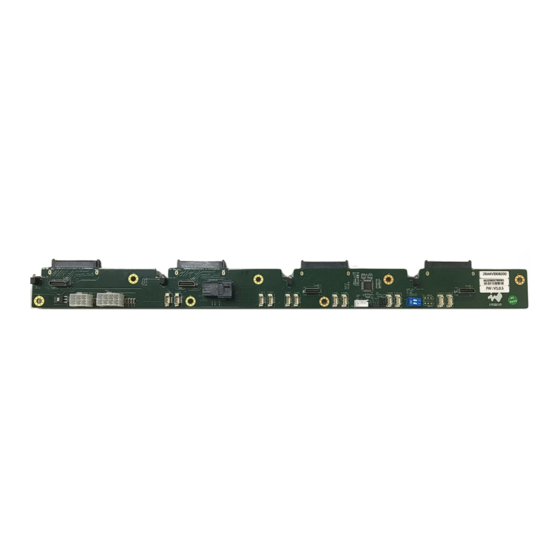
Page 6: Connector Locations And Led Indicators
Connector Locations and LED Indicators Description Description Host facing interface : NVME1~NVME4 Main Power Connector P W1/PW2 : Host facing interface (SAS3) : CN1 M/B Fan Speed Control : JM1 FAN Connector : FAN1~FAN12 Firmware Programming Header J D1 : Connector/ LED Indicators. -
Page 7: Connector Pin Definitions
Connector Pin Definitions. NVME1~NVME4 Power 2*3-Pin Connector PIN # Definition Ground Power 2*4-Pin Connector PIN # Definition +12V Ground Firmware Programming Connector PIN # Definition PIN No# Definition ICE_CLK ICE_DATA #Key ICE_RST Ground Model : IW-RS108-07 Hybrid Backplane User Manual PAGE 7 OF 14... -
Page 8: Hardware Specification
FAN1~FAN12 FAN 4-Pin Connector PIN # Definition PWM Output Tachometer +12V Ground M/B FSC 3-Pin Connector PIN # Definition MB_PWM BP_TACH Groubd Hardware Specification HOST Interface M iniSAS HD/OCulink : Hard Disk (SSD) Interface S ATA/SAS3/NVMe : Indicator : Power LED (PD1~PD4) : Blue –(When HDD is resent) Dual color(Green/Red) LED D1~D4 for Hard Disk Drive Status (Activity/Fail/Locate) Activity LED: Green (When HDD is Access) Fail/Locate LED : Red (When HDD Fail or Locate) -
Page 9: Led Behavior
LED Behavior Disk Bay LED Blue LED: Disk Insertion Indicator – Turned on whenever disk drive is properly installed. Green LED: Activity indicator – Stay off when idle and blinking (~8 Hz) whenever disk drive is being accessed. RED LED: Fail and Locate indicator –... -
Page 10: System Alarm Led
For NVMe application, The LEDs behave according to the VPP over I2C signals from NVMe host controllers through sideband bus of Oculink or SlimSAS cables. Whenever the NVMe host controller support VPP over I2C, the RED LEDs behave Locate, Fail and Rebuild signals following VPP signals on the I2C bus. -
Page 11: Smart Fan Control
Fail LED stays steady on when both events triggered at the same time. Smart Fan Control InWin’s Backplane is implemented Smart Fan Control feature by automatically detecting the existences of the Fan Modules and intelligently control the Fan RPM per the system temperature being detected by two thermal sensors (RTB1/RTB2) on the backplane. - Page 12 3. The 8 levels of fan speed are mapped to the temperature readings detected by thermistor spreading from 25 to 45 in 3.75 degree C step. ° C 4. In normal operation, when the system temperature changes to next level, the fan module would change speed accordingly.
-
Page 13: Firmware Upgrade
Firmware Upgrade The passive backplanes are planted Nuvoton M058 series MCUs for hosting disk LED indication, Fan speed control and system fail alarm. These MCUs are preprogrammed in manufacturing. In most cases, the MCUs are not required to reprogram unless there is issue needed to fix. - Page 14 3. Make sure device is connected and select the binary file being programmed and then click on Start button to program firmware. 4. Please refer to http://www.nuvoton.com/resource- files/NuLink_Adapter_User_Manual_EN_V1.01.pdf for more details. Model : IW-RS108-07 Hybrid Backplane User Manual PAGE 14 OF 14...
Need help?
Do you have a question about the IW-RS104-07 and is the answer not in the manual?
Questions and answers