
Subscribe to Our Youtube Channel
Related Manuals for InWin IW-RT04-01


Summary of Contents for InWin IW-RT04-01
- Page 1 Model Name :IW-RT04-01 User’s Manual Version : V1.0 Model : PCIe Retimer Card User’s Manual PAGE 1 OF 7...
- Page 2 Revision History Version Changes Date V1.0 Official Release 2021/02/18 Model : PCIe Retimer Card User’s Manual PAGE 2 OF 7...
- Page 3 Table of CONTENTS Overview ----------------------------------------------------------------------------------------------- 4 Physical Outlook ------------------------------------------------------------------------------------- 4 Mechanical -------------------------------------------------------------------------------------------- 5 Hardware Specification ---------------------------------------------------------------------------- 5 Connector Locations and Details View--------------------------------------------------------- 6 Jumpers. ----------------------------------------------------------------------------------------------- 6 Installation --------------------------------------------------------------------------------------------- 7 Model : PCIe Retimer Card User’s Manual PAGE 3 OF 7...
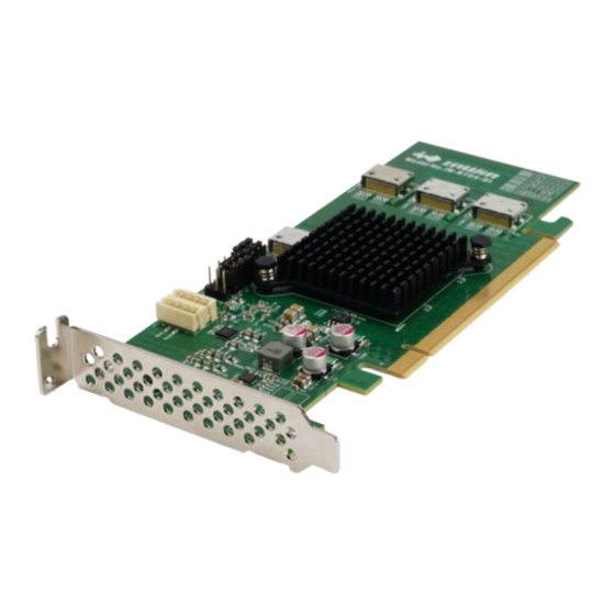
- Page 4 Overview The PCIe Retimer AIC is mainly designed to bridge the connections between x16 PCIe Slot host on Motherboard to 4 x4 NVMe SSDs on backplane. Alternately, the add-in-card supports connecting to x8 or x16 devices as PCIe signal integrator. The link speed of the HBA can support up to PCIe Gen3 speed, says 8Gb/s.
- Page 5 Mechanical Hardware Specification General : Quad port PCI-E x16 Gen-3 Retimer Four lanes per each OCuLink port support up to 32Gbps per port Supports four physical NVMe devices Operating temperature from 10°C - 55°C Pure HBA ...
- Page 6 Connector Locations and Details View Description Description J15 : NMVe0 Oculink Connector J7/J8/J9 : PCIe Mode Selection J16 : NVMe1 Oculink Connector J3/J4/J5 : SMBus Address Configuration J17 : NVMe2 Oculink Connector J10/J11 : VPP I2C Connector J18 : NVMe3 Oculink Connector JN1 : VPP Bus Selector Jumpers.
- Page 7 PCIe Mode Selection PCIe Mode Selection (1-2)=1 (2-3)=0 Mode x8x8 x8x4x4 x4x4x8 X4x4x4x4 Default: x4x4x4x4 Installation Electrostatic Discharge Sensitive (ESDS) Electrostatic Discharge (ESD) might damage electronic components. To prevent your Retimer card from being damaged, it is important to handle it with care. The following measures are generally sufficient to protect your device from ESD.
Need help?
Do you have a question about the IW-RT04-01 and is the answer not in the manual?
Questions and answers