Table of Contents
Advertisement
Quick Links
Advertisement
Table of Contents

Related Manuals for InWin IW-RS108-07


Summary of Contents for InWin IW-RS108-07
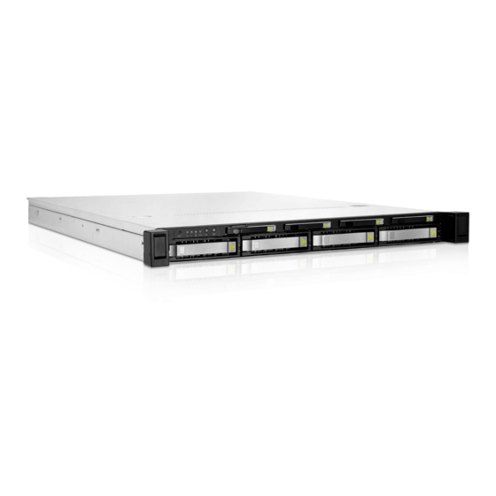
- Page 1 IW-RS108-07 User Manual 1U NVMe Hybrid Storage Server...
- Page 2 InWin’s server website. SAFETY INFORMATION To ensure a safe and smooth operation of your InWin IW-RS108-07, it is essential that you choose an appropriate location for the system, provide an appropriate operating environment and supply an adequate amount of power for all components of the system.
- Page 3 Installing or Removing Jumpers: A jumper is a short length conductor used to close, open or bypass part of an electronic circuit. Jumpers on InWin backplanes have a small tab on top that you can pick up with your fingertips. Grip the jumper carefully and plug the jumper to cover the jumper pins on the backplane.
-
Page 4: Product Introduction
1 Product Introduction 1.1 Box Contents When you open the IW-RS108-07 box, the contents should include following:... - Page 5 1.2 Accessories Box Item Item • Motherboard Screws x 11 Power LED 3-pin to 2-pin Adapter x 1 • Motherboard Stand-off Sockets x 11 2.5" HDD Screws x 28 HDD Tray Mark Label x 1 I/O Shield Screws x 2 Cables Ties and Mounts x 5 •...
-
Page 6: General Information
1.3 General Information When you open the chassis, it should reflect the diagram’s image. 3.5"/2.5" (15mm) hot-swap trays x 4 Top cover Top cover screwless open button Slide rail mounting area Top layer backplane 40 x 56mm PWM easy-swap fans x 6 Bottom layer backplane ATX, CEB, EEB M/B mounting area Front controls and indicator... - Page 7 1.3.1 Front Panel Controls and Indicators The IW-RS108-07 supports maximum 8 x hot-swappable 2.5"/3.5" NVMe/SAS/SATA disk bays, including 4 x 3.5"/ 2.5" (15mm) drive bays and 4 x 2.5" (7mm) drive bays in specific areas. The control panel, indicators are located on the Front Panel.
-
Page 8: Rear Panel Configuration
Power Supply Window reference InWin compatibility list to select the compatible models. System I/O InWin offers a customized service for 1U I/O shield. For more (Depends on M/B Specifications) Information, please contact InWin’s sales reps. The slot supports standard high profile cards. The bracket should be Full-Height PCIe Slot x 1 removed before using. -
Page 9: Hardware Installation
07 Series Motherboard & Expansion Card. For a quick installation video, please visit HDD Tray Installation The IW-RS108-07 features tool-less trays. Users no longer need to use screws to mount disks, and can swap drives faster. 07 Series HDD Tray Installation. - Page 10 ● 2.4.1 Power Supply Cable Information Single PSU Cable Information 500W Single PSU Cable Information 400mm 24 Pin Main Motherboard 500mm 8 Pin CPU 500mm 8 Pin CPU 400mm 8 Pin BP 600mm 6 Pin BP 400mm 5 Pin BP 450mm PMBus Length Unit: mm...
- Page 11 Redundant PSU Cable Information 750W Redundant PSU Cable Information 420mm 24 Pin Main Motherboard 200mm 8 Pin CPU 270mm 8 Pin CPU 530mm 8 Pin BP 300mm 6 Pin BP 300mm 5 Pin BP 500mm PMBus Length Unit: mm...
-
Page 12: Connecting Cables
2.5 Connecting Cables Connecting LED Cable, Front Control Panel Refer to your motherboard user guide for pin functions and locations, and then plug the connectors to the pins on the motherboard to activate the functions. RESETSW LANLED1 LANLED2 HDD LED SYS LED ID LED ID SW... - Page 13 2.6 Installing the Slide Rail The IW-RS108-07 is a rackmount model, which supports EIA-RS310D standard cabinets and chassis racks. InWin provides standard slide rails to allow users to mount the chassis onto the cabinets. 2.6.1 Identifying the Slide Rail The slide rail by your order might be different. You can reference the quick installation guide inside the slide rail package and follow the instructions to mount the rail onto your cabinet or chassis rack.
- Page 14 Step 3 2.6.4 Mounting the Rail Bracket to the Cabinet Step 1: Extend the rail bracket over the rear rack of the cabinet. Step 2: Pull out the rear hook on the end of the outer rail, align and push the rail bracket pins into the post holes on the rack.
- Page 15 2.6.5 Inserting the Chassis to the Cabinet Step 1: Pull out the middle rail to the stop position. Step 2: Move the ball bearing retainer to the front end of the middle rail, and it should click into the locked position. Step 3: Insert the inner rails of the chassis into the middle rails on both sides of the rack.
-
Page 16: Backplane Introduction
6Gbps, SATA 6Gps and SATA 3Gps HDD/SSD. The backplane supports NVMe SSD through OCuLink x 8 connectors. The backplane varies by order. Please reference the backplane user guide to complete the installation. The download link is at the download section of each product. Please visit the InWin website: ipc.in-win.com. - Page 17 Backplane Connection The IW-RS108-07 supports NVMe SSDs through OCuLink x 8 connectors, and the backplane is backward compatible with Mini-SAS HD. 3.3.1 OCuLink Backplane Connection Please use the SFF-8611 cable to connect to the motherboard or RAID/HBA controller card. One of the OCuLink connectors is only used for SAS/SATA data transfer rates.
-
Page 18: Compatibility Lists
InWin’s chassis. You can download the latest updated device compatibility list from InWin’s website: ipc.in-win.com 5 Technical Support If you need help with installation or troubleshooting, you can contact your local InWin reps, or send an e-mail to InWin’s local contacts for technical assistance. - Page 19 Copy r i g ht © I n W in D eve lo p m ent I n c . A l l Ri g ht s Res e r ved .
Need help?
Do you have a question about the IW-RS108-07 and is the answer not in the manual?
Questions and answers