
Related Manuals for UE Systems UE ECM-586


Summary of Contents for UE Systems UE ECM-586
- Page 1 Version 1 UE ECM - 586 UE WIDE BAND ULTRASONIC DETECTION SENSOR Instruction Manual...
-
Page 2: Table Of Contents
Version 1 OVERVIEW ............................... 3 ULTRASOUND TECHNOLOGY ........................4 UE ECM-1 INSTALLATION & OPERATION ..................... 5 POWER REQUIREMENTS ........................5 SENSITIVITY CONTROL ......................... 5 THRESHOLD CONTROL ......................... 5 VOLTAGE AND CURRENT OUTPUTS ..................... 5 HETERODYNED AUDIO OUTPUT ......................6 ALARM OUTPUT ..........................6 SYSTEM SETUP ............................. -
Page 3: Overview
Version 1 OVERVIEW The UE ECM-1 is an Ultrasonic Detection unit that is targeted for continuous monitoring. The unit offers an overall dynamic range of roughly 100 decibels, and is configured for air borne ultrasonic detection. -
Page 4: Ultrasound Technology
Version 1 ULTRASOUND TECHNOLOGY The Ultrasound Technology utilized by this system is generally referred to as “Airborne Ultrasound”. Airborne Ultrasound is concerned with the transmission and reception of ultrasound through the atmosphere without the need of sound conductive (interface) gels. It incorporates methods of receiving signals generated through one or more media via wave signals. -
Page 5: Ue Ecm-1 Installation & Operation
Version 1 UE ECM-1 INSTALLATION & OPERATION POWER REQUIREMENTS The UE ECM-1 requires a 24 Volt, DC power source @ 200 milliamperes total. The power connections are to be made to the I/O cable. Refer to the Pin Out/Description Diagram for the connections. -
Page 6: Heterodyned Audio Output
Version 1 HETERODYNED AUDIO OUTPUT The sensor provides an audio output for use with a speaker or a pair of headphones. The signal can also be fed into a spectrum analyzer for waveform analysis. The output level is preset at the Factory @ 90 dBA for the full scale output. -
Page 7: Panel Indicators
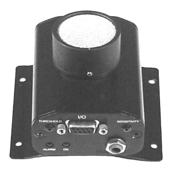
Version 1 PANEL INDICATORS: FUNCTION Blue ECM-1 Powered Up & Ok to Monitor Alarm Red = Alarm Condition PANEL Adjustments: Sensitivity Adjust Alarm Set Point (Threshold) Adjustment The Sensitivity Adjust is located on the front panel. Use a screwdriver and turn the adjustment screw clockwise to increase and counter-clockwise to decrease the sensitivity. - Page 8 Version 1 3.6875" . 3.3125" 2.50" 3.625" TYP. (4) HOLES .1875" DIA...
-
Page 9: Evaluating Wave Files To Determine The Severity Of The Ultrasonic Emissions
Version 1 EVALUATING WAVE FILES TO DETERMINE THE SEVERITY OF THE ULTRASONIC EMISSIONS We are often asked at which voltages and on what type of equipment is ultrasound most effective. The answer is not simple since it often depends on the individual asking the question. First of all, determining the definition of low, mid and high voltages is relative. -
Page 10: Analysis Of Recorded Signals
Version 1 ANALYSIS OF RECORDED SIGNALS While it is relatively easy to determine arcing, tracking or corona by the sound pattern, there can be occasions where it may prove confusing. It may be possible that a strong buzzing sound related to corona might in fact be nothing more than mechanical looseness. -
Page 11: Corona
Version 1 EXAMPLE OF DISCHAGE POINTS FOR CORO CORONA Note that the discharge points only occur at the highest voltage point of the sine wave. This means that the amplitude peaks in the Time Domain are somewhat equally spaced as the discharges are only at the positive peak of the sine wave. -
Page 12: Corona Spectrum
Version 1 CORONA SPECTRUM... -
Page 13: Corona Time Series
Version 1 CORONA TIME SERIES... -
Page 14: Tracking Spectrum
Version 1 TRACKING SPECTRUM... -
Page 15: Tracking Time Series
Version 1 TRACKING TIME SERIES... -
Page 16: Arcing Spectrum
Version 1 ARCING SPECTRUM... -
Page 17: Arcing Time Series
Version 1 ARCING TIME SERIES... -
Page 18: Loose Component Spectrum
Version 1 LOOSE COMPONENT SPECTRUM... - Page 19 Version 1 Need further support? Want information regarding products or training? Contact : UE Systems Europe, Windmolen 20, 7609 NN Almelo (NL) info@uesystems.eu www.uesystems.eu t: +31 (0)546 725 125 f: : +31 (0)546 725 126 www.uesystems.eu...
Need help?
Do you have a question about the UE ECM-586 and is the answer not in the manual?
Questions and answers