Table of Contents
Advertisement
Quick Links
Advertisement
Table of Contents

Subscribe to Our Youtube Channel
Related Manuals for UE Systems ULTRAPROBE 9000


Summary of Contents for UE Systems ULTRAPROBE 9000
- Page 1 UE SYSTEMS INC. THE ULTRAPROBE 9000 MANUAL...
-
Page 2: Table Of Contents
TABLE OF CONTENTS OVERVIEW Introduction Operation Mode Setup Mode COMPONENTS Basic components of your kit Plug-In Modules Scanning Module Contact Module Pistol Grip Housing Display Panel Trigger On/Off Switch I/O Port Battery Compartment/Battery Wrist Strap Sensitivity Control Dial Storage Entry Button Head Set Jack Recharge Jack ACCESSORIES... - Page 3 OPERATION MODE Display Panel Bar Graph Display Sensitivity Control Dial Sensitivity / Volume Adjust Frequency Adjust Yellow Store Button Store a Reading Overwrite Data or Enter Data in a New Location To Download the Information SETUP MODE Text Editor Data Transfer Set Time &...
-
Page 4: Overview
OVERVIEW INTRODUCTION The Ultraprobe 9000 is a versatile instrument with many features that will make for easy, fast, and accurate ultrasonic inspections. As with any new instrument, it is important to review this manual before starting any inspection program. THERE ARE TWO MODES THAT ARE IMPORTANT TO UNDERSTAND: OPERATION MODE: The operation mode will be described in detail under the operation mode section. -
Page 5: Components
COMPONENTS BASIC COMPONENTS OF YOUR KIT I/O Cable Stethoscope Extension Kit Charger Warble Tone Generator Scanning Module Pistol Grip Housing Headphones Wrist Strap Stethoscope Module Rubber Focusing Probe PLUG-IN MODULES TRISONIC SCANNING MODULE. This module is utilized to receive airborne ultrasound such as the ultrasounds emitted by pressure/vacuum leaks and electrical discharges. -
Page 6: Display Panel
STETHOSCOPE (CONTACT) MODULE. This is the module with the metal rod. This rod is used as a "waveguide" in that it is sensitive to ultrasound that is generated internally such as within a pipe, bearing housing or steam trap. Once stimulated by ultrasound, it transfers the signal to a piezoelectric transducer located directly in the module housing. -
Page 7: Recharge Jack
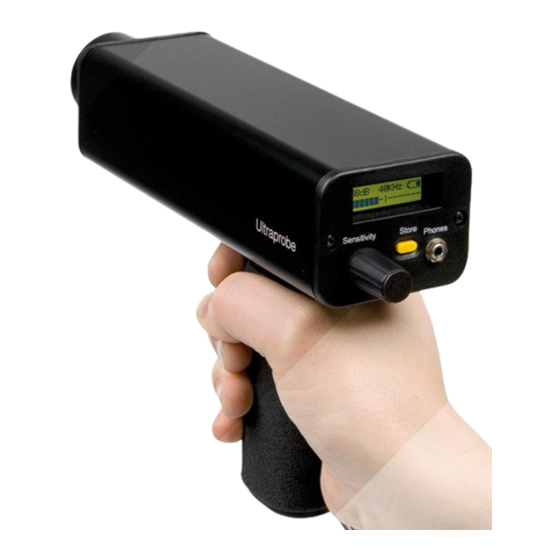
Module Sensitivity Dial Trigger Wrist Strap TRIGGER ON/OFF TRIGGER SWITCH. The Ultraprobe is always "off' until the trigger is pulled. To operate, press and hold the trigger. To turn the instrument off, release the trigger. SENSITIVITY CONTROL DIAL. This is one of the most important controls in the unit. In the operation mode, this dial is used to adjust the sensitivity. -
Page 8: Accessories
STORAGE ENTRY BUTTON. This yellow button is used to store data. HEADSET JACK. This is where the headset is plugged in. Be sure to plug it in firmly until it clicks. ACCESSORIES STANDARD ACCESSORIES HEADSET. This heavy-duty headset is designed to block out intense sounds often found in industrial environments so that the user can focus on the sounds received by the Ultraprobe. -
Page 9: Stethoscope Extension Kit
UP9000 with a line input of 120/240 VAC @ 60/50Hz. The charging time is about 8 hours. The charger comes with adaptors for multiple world regions. The black lead is for the Ultraprobe 9000. WTG BATTERY CHARGER . This is the standard battery charger for all Warble Tone Generators that are used with the UP9000. - Page 10 OPERATION MODE DISPLAY PANEL When the trigger is pressed to turn the instrument on, the Display Panel will display intensity levels simultaneously on a bar graph and as a numerical decibel value. The current selected frequency will also be shown. Remaining Battery Charge is shown in the upper right corner. The letters R, S, or P will alternate with the battery indicator in the upper right corner.
- Page 11 Once in the Sensitivity mode, turn the Sensitivity dial clockwise to increase the sensitivity and counter clockwise to decrease the sensitivity. The Sensitivity control dial increases/decreases the sensitivity of the instrument simultaneously with the sound level in the headphones. The instrument needs to be in range for accurate testing. NOTE: If the sensitivity is too low, a blinking arrow pointing to the right will appear and there will be no numeric decibel visible in the display panel.
- Page 12 THE YELLOW STORE BUTTON TO STORE A READING Press the yellow Store button. This puts the instrument in the data storage mode. In the data storage mode, the display panel will change. The Storage Location is shown in the upper left corner. There are 400 Storage Locations numbered 001 to 400.
- Page 13 TO DOWNLOAD THE INFORMATION Refer to Setup Mode, 01 Data Transfer TEXT EDITOR TO ENTER TEXT IN THE TEXT FIELD If enabled (refer to SET UP MODE 07), Press the yellow Store Button once after storing data The text field will blink. If the field has no entry, it will display “UNKNOWN” and the first character will blink.
- Page 14 When in the first Menu mode: “Data Transfer,” it is possible to move to any of the other Menu modes by spinning the Sensitivity Control up or down (clockwise or counter clockwise). When the desired Menu mode is reached, push (Click) the Sensitivity Control in. It is possible to spin to enter and exit any Menu mode in the Set Up mode if the trigger on/off switch is pressed.
- Page 15 Click to set. When finished, Spin the Sensitivity dial until “EXIT” flashes. Click the Sensitivity dial again and return to the Set Up Mode. Spin to “Exit to PGM” (Exit to Program) (Menu 10) blinks. Click to enter Operation Mode To change date format from US to International Standard see Menu 08 Date Format.
- Page 16 MENU 04 dB OFFSET This position is selected to set the dB scale for readings to be taken in dB offset scale. In order to use the dB offset scale, refer to Menu 03 instructions above. TO SET THE dB OFFSET SCALE Make sure the Ultraprobe is off.
- Page 17 MENU 05 DISPLAY MODE THERE ARE THREE MODES TO CHOOSE IN DISPLAY MODE: REAL TIME, SNAPSHOT AND PEAK HOLD Real Time is the standard operation of the instrument. For basic inspection operations choose Real Time. Snapshot is a very useful mode for inspections that require a comparison of measurements.
- Page 18 MENU 06: CALIBRATION DUE DATE Shown as “Cal Due Date” in the menu, this date is set at the factory and displays the recommended Recalibration/service date. This is one mode that cannot be changed by a user. It is only set at the factory after a service has been performed. MENU 07: TEXT EDITOR Text editor will enable or disable text entry when a reading is to be saved during the operation mode.
- Page 19 MENU 08: DATE FORMAT Date format can be changed from the US (month/day/year) to the international: (day/month/year). TO CHANGE THE DATE FORMAT Make sure the Ultraprobe is off. Press (click) both the yellow Store button and the Sensitivity dial at the same time, then squeeze and hold the trigger.
- Page 20 MENU 09: FACTORY DEFAULTS This mode allows users to retain or to delete the information stored in the instrument and to restore the factory default settings of the instrument. Confirm = YES means that the onboard computer will default to original factory settings and all stored data will be deleted. Confirm = NO retains all stored data and current instrument settings.
- Page 21 USERS INSTRUCTIONS TRISONIC SCANNING MODULE Plug in to front end Align the pins located at the rear of the module with the four jacks in the front end of the Metered Pistol Housing (MPH) and plug in. Start to scan the test area HEADPHONES To use, firmly plug the headphone jack into the “Phones”...
-
Page 22: Ras-Mt
STETHOSCOPE EXTENSION KIT Remove the Stethoscope Module from the Metered Pistol Housing. Unscrew the metal rod in the Stethoscope Module. Choose the rod that is the middle length of the three this is the "base piece". Screw the Base Piece into the Stethoscope Module. If all 31"... - Page 23 WARNING: Only use the supplied UE Systems recharger. Use of unauthorized rechargers will void the warranty and may damage the battery and or instrument. WARBLE TONE GENERATOR (UE WTG 1) Turn Tone Generator on by selecting either "LOW" for a low amplitude signal (usually recommended for small containers) or "HIGH"...
- Page 24 INSTRUCTIONS FOR SETTING COMBINATION ON CARRYING CASE The combination is factory set at --0--0--0 SETTING YOUR PERSONAL COMBINATION Open the case. Looking at the back of the lock inside the case you will see a change lever. Move this change lever to the middle of the lock in a way that allows it to hook behind the change notch (drawing 1).
- Page 25 Need further support? Want information regarding products or training? CONTACT: UE Systems, Inc. 14 Hayes Street, Elmsford, NY 10523 USA 914-592-1220 | info@uesystems.com | www.uesystems.com...
Need help?
Do you have a question about the ULTRAPROBE 9000 and is the answer not in the manual?
Questions and answers