Table of Contents
Advertisement
Advertisement
Table of Contents

Related Manuals for Umano Medical ooksnow FL36


Summary of Contents for Umano Medical ooksnow FL36
- Page 1 FL36 User manual 2 0 1 7 / 1 0 | 7 4 - 3 6 1 0 5 - E N G R 5...
- Page 3 FL36 User manual 2 0 1 7 / 1 0 | 7 4 - 3 6 1 0 5 - E N G R 5...
- Page 4 Copyright 2017 Umano Medical Inc. All Rights Reserved. No part of this publication may be reproduced, distributed, or transmitted in any form or by any means, including photocopying, recording, or using electronic or mechanical methods, without the prior written permission of the publisher, except in the case of brief quotations embodied in critical reviews and certain other noncommercial uses permitted by copyright law.
-
Page 5: Table Of Contents
TABLE OF CONTENTS INTRODUCTION Power cord support brackets ....29 ........5 Short power cord (optional) .....30 Product description ........5 CPR release (optional) ......30 Product intended use ........5 Nurse call connector (optional) ....30 Contact ............5 Auxiliary power outlets and USB port (optional) ..........31 Product illustration ........7 Communication port (optional) ....32 Technical specifications ......8... - Page 6 1" fixed IV pole for 3/4" socket - FA64522 ............79 1" fixed IV pole for 1" socket - FA64508 ..80 Left 1" folding IV pole for 1" socket - FA64521 ............81 Right 1" folding IV pole for 1" socket - FA64523 ............82 Oxygen bottle holder - FA64505 ....83 Patient helper - FA64504 ......84...
-
Page 7: Introduction
The manufacturer can be contacted for any assistance regarding the set up or the use of the bed, its maintenance or to report unexpected events at: Umano Medical Inc. 230 boulevard Nilus-Leclerc, L’Islet QC G0R 2C0 CANADA T: (418) 247-3986 T: (844) 409-4030 information@umanomedical.com... - Page 8 INTRODUCTION Application environments Description ook<snow>> Intensive/critical care provided in a hospital where 24 h medical supervision and constant monitoring is required and provision of life support system/equipment Applicable* used in medical procedures is essential to maintain or improve the vital functions of the patient.
-
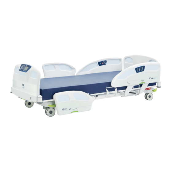
Page 9: Product Illustration
INTRODUCTION Product illustration Item Description Item Description Headboard Backrest section CPR release handle (optional) Nurse call plug (optional) Power cord Siderail control Angle indicator Brake, neutral and steer pedal Drainage bag support Siderail release handle Patient siderail control Footboard Footboard control Bumper Frame control (optional) Bed extender handle (optional) -
Page 10: Technical Specifications
INTRODUCTION Technical specifications Weights and dimensions Bed weight (based on features) 375 lb to 438 lb 170 kg to 199 kg Safe working load (including patient, mattress and 500 lb 227 kg accessories) Maximum mattress weight 44 lb 20 kg Maximum accessories weight 100 lb 45 kg... - Page 11 INTRODUCTION Environmental conditions 50 °F to 104 °F 10 °C to 40 °C ambient temperature 5 to 95% without 5 to 95% without relative humidity condensation condensation atmospheric pressure 500 to 1060 hPa 500 to 1060 hPa Transport and storage ambient temperature -40 °F to 158 °F -40 °C to 70 °C...
-
Page 12: Emc Information
INTRODUCTION EMC information Guidance and manufacturer’s declaration - emission The “FL36 Medical Bed” is intended for use in the electromagnetic environment specified below. The customer or user of the “FL36 Medical Bed” should ensure that it is used in such an environment. Emission test Compliance Electromagnetic environment - guidance... - Page 13 INTRODUCTION Guidance and manufacturer’s declaration - immunity The “FL36 Medical Bed” is intended for use in the electromagnetic environment specified below. The customer or user of the “FL36 Medical Bed” should ensure that it is used in such an environment. Electromagnetic Immunity test IEC 60601 test level...
-
Page 14: Symbols And Definitions
INTRODUCTION Symbols and definitions Different symbols are used on the product and in this manual. Their purpose is to inform the user on functional details or on safety related measures. Indicates the need for the user to consult the instructions for use for Indicates the medical device cautionary information such as manufacturer... - Page 15 INTRODUCTION Indicates the need for the user to Indicates the need for the user to consult instructions for use follow instructions for use Indicates that the equipment has been Indicates a general mandatory action independently tested and meets the applicable published safety standard Indicates that when disposed, the equipment must be collected separately in accordance with the...
-
Page 16: Pictograms And Definitions
INTRODUCTION Pictograms and definitions Different pictograms are used on the product and in this manual. Their purpose is to facilitate the reading and the understanding of the different functionalities to the user. If bed is equipped with screen, additional pictograms may be displayed in different menus. - Page 17 INTRODUCTION Button for selection of bed exit Button with LED indicator for control degree of sensitivity for activation/deactivation, of bed exit Detection 1 - OUT-OF-BED control system Button for selection of bed exit Illustration indicating group of buttons for bed exit control system control degree of detection for settings Detection 2 - BED EXITING...
- Page 18 INTRODUCTION Illustration indicating location for Illustration indicating location for communication port nurse call connector Illustration indicating that patient Illustration indicating necessity to monitor blood sugar level has one or more allergies Illustration indicating a patient Illustration indicating interdiction to drink liquids subject to pressure ulcers Illustration indicating patient is Illustration indicating interdiction...
-
Page 19: Safety Measures
INTRODUCTION Safety measures Terms DANGER, WARNING, ATTENTION and IMPORTANT are used in this manual to indicate important measures to take for use or maintenance of the equipment. The gradation, the definitions and safey measures shall be carefully reviewed and understood before use. Gradation and definition of safety measures DANGER Indicates an imminent hazardous situation, which if not avoided, will result in serious injury or death. - Page 20 INTRODUCTION WARNING • Grounding reliability can be achieved only when the bed is connected to a supply mains with protective ground or to a hospital grade outlet that is protectively grounded. • To avoid risk of electric shock hazard, bed must only be connected to a supply mains with protective ground or to a hospital grade outlet that is protectively grounded.
- Page 21 INTRODUCTION • If electrical equipment is connected to the auxiliary outlet or USB port, ensure that any electrical device introduced within the patient vicinity is not causing electrical interferences. The connected electrical equipment could results in power leads or radiation emitting devices closer to the patient (ex: computer charger, mobile phone) and their interference shall be managed to avoid biased diagnostics (ex: ECG monitors) or limited treatment efficiency (ex: pacemakers).
- Page 22 INTRODUCTION • This bed is not designed nor intended for a magnetic resonance imaging use. Use in intended environments only. • No modification to this equipment is allowed unless it is first approved by the manufacturer, performed by trained personnel, and then inspected and tested to ensure continued its continued safety. •...
-
Page 23: Getting Started
Bed must be properly installed and verified prior to be put in service. Refer to the list below to ensure proper set up. Steps list for set up 1. Perform a complete visual inspection of the bed. Contact Umano Medical or local representative if there are any damages or missing item. - Page 24 GETTING STARTED 17. If applicable, test the room lights functions for proper operation. 18. If applicable, verify following options for proper operation: bed extender, auxiliary power outlets and USB port, nightlights, etc. 19. If bed is equipped with bed exit detection, perform a zero procedure on the bed after all equipment has been installed.
-
Page 25: Zeroing Procedures
GETTING STARTED Zeroing procedures ATTENTION • Patient must be out of bed. Zeroing procedure for a bed with bed exit only Procedure: 1. Bed is electrically powered up. Ensure sleep surface is completely flat, siderails are raised and put the bed elevation system at intended height of use. - Page 26 GETTING STARTED Zeroing procedure for a bed with display screen with bed exit only Procedure: 1. Bed is electrically powered up. Ensure sleep surface is completely flat, siderails are raised and put the bed elevation system at intended height of use. Brakes are set. 2.
-
Page 27: Operating Instructions
OPERATING INSTRUCTIONS IMPORTANT Read and understand all information covered in this manual before operating the equipment. Users shall be knowledgeable about inherent hazards related to use of electric beds. Power up and modes of operation If a power failure occurs, bed will automatically fall in sleep mode and initiate the battery-powered mode. If the bed operates on batteries, the patient and caregiver controls for bed-motion will remain functional. -
Page 28: System Signals And Messages
OPERATING INSTRUCTIONS System signals and messages The hospital bed FL36 can issue a signal or a message to inform the user that an action is required. It can be visual and/or audible and/or textual if the bed is equipped of the display screen. Visual signal A visual signal may take the form of flashing LEDs on the membrane of the footboard for a bed equipped of a bed exit system. -
Page 29: Base, Frame And Litter
OPERATING INSTRUCTIONS BASE, FRAME AND LITTER The bed for mental care environments can be configured with casters and braking system, or with the option of floor mounted fixation. IMPORTANT The bed is equipped with base covers at head and foot ends of the bed. Base covers must be kept in place while bed is in use to preserve electrical and mechanical components. -
Page 30: Motion Interrupt (Optional)
OPERATING INSTRUCTIONS Motion interrupt (optional) The bed can be equipped with a motion interrupt system that detects an obstruction under the bed when the bed elevation system is being lowered. The system will then interrupt the bed motion. If bed is equipped with a display screen on footboard using software version 2.0, a message will appear in the display screen to indicate that an obstruction has been detected. -
Page 31: Reduced Ligature Attachment Points (Optional)
OPERATING INSTRUCTIONS Reduced ligature attachment points (optional) Bed can be equipped with the option of reduced ligature attachments points. To provide a reduction of the attachment points, the upper part of the central mattress retainer is filled and the lower part is removed. Also, the patient sleep surface will not offer the four mattress retainers (D)(E);... -
Page 32: Short Power Cord (Optional)
OPERATING INSTRUCTIONS Short power cord (optional) The power cord length can be adjusted to meet the needs and condition of a patient in a specific environment. The length of the short power cord is of 1 m / 40", but can be adjusted to a longer length if required. The label fixed on the power cord always needs to be visible to ensure that the minimum length allowed for this option is respected;... -
Page 33: Auxiliary Power Outlets And Usb Port (Optional)
OPERATING INSTRUCTIONS Auxiliary power outlets and USB port (optional) Optionally, bed can be equipped with 120V auxiliary power outlets and USB port intended to be used as convenient power source for patient and caregiver use to energize low power devices. Power outlets are limited to 5A or 600W, with protective earth terminal. -
Page 34: Communication Port (Optional)
OPERATING INSTRUCTIONS Communication port (optional) Bed can be equipped of a USB communication port intended to be used for software updates and/or bed diagnosis. IMPORTANT The communication port will not be functional if bed is unplugged. This communication port shall not be used as a power source for portable devices. Control on frame (optional) An optional control located on the frame, at the foot end of the bed, offers complementary functions to... -
Page 35: Bed Extender (Optional)
OPERATING INSTRUCTIONS Bed extender (optional) The optional bed extender allows the user to extend the length of the patient sleep surface from 80" to either 84" or 90". Usage of mattress extension cushion is required. WARNING • Siderails are designed to prevent patient to inadvertently fall from the bed. •... -
Page 36: Head And Foot Ends Siderails
OPERATING INSTRUCTIONS HEAD AND FOOT ENDS SIDERAILS WARNING • Siderails are designed to prevent patient of inadvertently fall from the bed. • Siderails are not designed nor intended for patient restraint. If not avoided, situation could result in patient injury. •... -
Page 37: Patient Mobilization Helper (Optional)
OPERATING INSTRUCTIONS Patient mobilization helper (optional) Bed is equipped with patient mobilization helper which operates with a release handle located at the bottom center of each patient mobilization helper. WARNING • Always ensure that patient is capable of proper usage of the patient mobilization helper to prevent patient to slip at foot end and avoid possible injuries caused by patient fall. -
Page 38: Patient Siderail Controls
OPERATING INSTRUCTIONS Patient siderail controls Patient siderail controls are located on the inside of each head siderail. Do not use sharp or small pointed objects on membranes to avoid permanent damages. Pictograms inform the user of positioning possibilities and features. ATTENTION •... -
Page 39: Caregiver Siderail Controls
OPERATING INSTRUCTIONS Caregiver siderail controls Caregiver siderail controls are located on the outside of each head siderail. Do not use sharp or small pointed objects on membranes to avoid permanent damages. Pictogram informs the user of positioning possibilities and features. IMPORTANT Refer to the pictograms and definitions... -
Page 40: Patient Control (Optional)
OPERATING INSTRUCTIONS Patient control (optional) Patient control can be used to allow patient or healthcare personel to activate certain bed functions. Do not use sharp or small pointed objects on membranes to avoid permanent damages. Pictograms inform the user of positioning possibilities and features. -
Page 41: Headboard And Footboard
OPERATING INSTRUCTIONS HEADBOARD AND FOOTBOARD Bed is equipped with a set of headboard and footboard. If patient’s medical condition requires to prevent tampering and abusive uses, and does not require intensive, critical or acute care, the headboard and footboard can be fixed to the frame and can help avoid inappropriate intentional or unintentional usage by the patient towards the environment, or towards oneself or others. -
Page 42: Footboard Control
OPERATING INSTRUCTIONS Footboard control Footboard control is located on the board at the food end of the bed. Do not use sharp or small pointed objects on membranes to avoid permanent damages. Pictograms inform the user of positioning possibilities and features. IMPORTANT Refer to the pictograms and definitions... - Page 43 OPERATING INSTRUCTIONS Standard configuration Bed motion lockout to the siderails controls can be set with one of the 3 closed padlock pictogram press buttons with integrated LED. A solid amber LED ON indicates that bed motion illustrated below is locked in the siderails, the bed motions can still be activated from the footboard control panel.
- Page 44 OPERATING INSTRUCTIONS Bed exit control system The patient risk (or fall risk) management functionalities offer a volume range that can be set with the press button illustrated with the loudspeaker pictogram. The LED indicator by one of the 4 levels will indicate if volume is OFF, low, medium or high.
-
Page 45: Footboard Control With Display Screen
OPERATING INSTRUCTIONS Footboard control with display screen Navigation buttons are associated with the menu displayed above in the screen. Menus highlighted in Home blue are associated with actions whereas menus in grey November 1st 12:00 are not and cannot be selected in this specific screen. 0 º... -
Page 47: Detailed Screen Functions (Sw 1.3)
OPERATING INSTRUCTIONS Detailed screen functions (SW 1.3) The following section details the screen functions for bed equipped with software version 1.3. The software version can be verified through Preference screen in Maintenance menu. USER MANUAL — 74-36105-ENG R5... - Page 48 OPERATING INSTRUCTIONS Home screen Screen informs the user of the height and the angulations of patient sleep surface. User can return to the Home screen menu at any time by pressing on the Home button. IMPORTANT The bed height is rounded up. The angulations accuracy of backrest section is +/- 2 The angulations accuracy of Trendelenburg and reverse-Trendelenburg is +/- 2 A simplified interface displaying less options is offered for a simplified use.
- Page 49 OPERATING INSTRUCTIONS Home screen with integrated scale (optional) The functions Arm (Disarm), Auto Arm, Fall Risk management and Preference of a bed configurated with the scale option operate as detailed in the Home screen section (page 46). Refer to this section if needed. IMPORTANT The bed height is rounded up to the closest unit.
- Page 50 OPERATING INSTRUCTIONS Fall risk management screen menu Navigate and select: • Set Detection to access the bed exit detection Fall Risk Management settings. The displayed pictogram informs of November 1st 12:00 the pre-selected detection level. • Alarm Settings to access the volume range and the tone selection.
- Page 51 OPERATING INSTRUCTIONS Set Detection screen menu The displayed pictogram informs of the pre-selected detection level. The ARM button will change to DISARM if the bed exit control system is activated. Navigate and select: • Detection 1 to change level of detection to a Bed Exit Detection settings patient out-of-bed.
- Page 52 OPERATING INSTRUCTIONS Inform screen menu The Inform screen menu offers the possibility to set a screen saver with display of the different pictograms selected from the Pictograms library to inform caregivers of patient condition and predisposition to fall, and/or display of required siderails configuration. The screen also offers possibility to set a color-coding with 1, 2 or 3 different colors.
- Page 53 OPERATING INSTRUCTIONS • Siderails configuration to set screen saver with display of required siderails configuration on the pictogram displayed on screen saver. Background of button turns green once configurated and activated. Configuration steps: From the Inform menu, press the siderails Siderails configuration configuration button.
- Page 54 OPERATING INSTRUCTIONS Preference screen If applicable a short cut to Errors log will be prompted Home If pre-set, a short cut to Lock of motion and to Inform November 1st 12:00 will be prompted. Other preferences settings are accessible under Pref. 0 º...
- Page 55 OPERATING INSTRUCTIONS Brightness screen Select: • UP arrow for Screen brightness and select Lights Brightness one of four levels of intensity. November 1st 12:00 • UP arrow for Nightlight brightness and select Screen Nightlight SideView one of three levels of intensity or set to OFF. Lights •...
- Page 56 OPERATING INSTRUCTIONS Identification screen Use the ID feature in the Identification screen to label the equipment with a color code and text. The label will display over the date and time in the Home screen. A maximum of 20 digits can be entered as a text label. Select: •...
- Page 57 OPERATING INSTRUCTIONS Scale screen For proper use of scale related features, ensure bed is not interfering with any item of the environment or in contact with wall. Do not touch bed. Select: • Scale to display and log patient weight. Select Scale Weight to display weight.
-
Page 59: Detailed Screen Functions (Sw 2.0)
OPERATING INSTRUCTIONS Detailed screen functions (SW 2.0) The following section details the screen functions for bed equipped with software version 2.0. The software version can be verified through Preference screen in Maintenance menu. USER MANUAL — 74-36105-ENG R5... - Page 60 OPERATING INSTRUCTIONS Home screen Screen informs the user of the height and the angulations of patient sleep surface. User can return to the Home screen menu at any time by pressing on the Home button. IMPORTANT The bed height is rounded up. The angulations accuracy of backrest section is +/- 2 The angulations accuracy of Trendelenburg and reverse-Trendelenburg is +/- 2 A simplified interface displaying less options is offered for a simplified use.
- Page 61 OPERATING INSTRUCTIONS Home screen with integrated scale (optional) The functions Arm (Disarm), Auto Arm, Patient Risk management and Preference of a bed configurated with the scale option operate as detailed in the Home screen section (page 58). Refer to this section if needed. IMPORTANT The bed height is rounded up to the closest unit.
- Page 62 OPERATING INSTRUCTIONS Care Pause When the bed exit detection is armed, press the Disarm Detection button to apply a Care Pause and give the caregiver 5 minutes to provide any care to the patient without disactivating the bed exit system and without generating a bed exit detection alarm.
- Page 63 OPERATING INSTRUCTIONS Patient risk management screen menu Navigate and select: • Set Detection to access the bed exit detection Patient Risk Management settings. The displayed pictogram informs of November 1st 12:00 the pre-selected detection level. • Alarm Settings to access the volume range and the tone selection.
- Page 64 OPERATING INSTRUCTIONS Set Detection screen menu The displayed pictogram informs of the pre-selected detection level. The ARM button will change to DISARM if the bed exit control system is activated. Navigate and select: • Detection 1 to change level of detection to a Bed Exit Detection settings patient out-of-bed.
- Page 65 OPERATING INSTRUCTIONS Inform screen menu The Inform screen menu offers the possibility to set a screen saver with display of the different pictograms selected from the Pictograms library to inform caregivers of patient condition and predisposition to fall, and/or display of required siderails configuration. The screen also offers possibility to set a color-coding with 1, 2 or 3 different colors.
- Page 66 OPERATING INSTRUCTIONS • Siderails configuration to set screen saver with display of required siderails configuration on the pictogram displayed on screen saver. Background of button turns green once configurated and activated. Configuration steps: From the Inform menu, press the siderails Siderails configuration configuration button.
- Page 67 OPERATING INSTRUCTIONS Patient risk management log screen The Patient Risk Management Log offers a log listing up to 100 entries related to activation and deactivation of features. Entries related to bed exit control are highlighted in green to indicate activation and highlighted in orange to indicate an alarm.
- Page 68 OPERATING INSTRUCTIONS Preference screen If applicable a short cut to Errors log will be prompted Home If pre-set, a short cut to Lock of motion and to Inform November 1st 12:00 will be prompted. Other preferences settings are accessible under Pref. 0 º...
- Page 69 OPERATING INSTRUCTIONS Lights configuration screen Select: • UP arrow for Screen brightness and select Lights Configuration one of four levels of intensity. November 1st 12:00 • UP arrow for Nightlight brightness and select Screen Nightlight SideView one of three levels of intensity or set to OFF. Lights •...
- Page 70 OPERATING INSTRUCTIONS Identification screen Use the ID feature in the Identification screen to label the equipment with a color code and text. The label will display over the date and time in the Home screen. A maximum of 20 digits can be entered as a text label. Select: •...
- Page 71 OPERATING INSTRUCTIONS Min. Height Adjustment The minimum height adjustment screen offers to set minimum bed height depending on the needs of the caregiver or of the patient. When the bed’s lowest height is reached, a “min. height” indication will appear on the Home Screen.
- Page 72 OPERATING INSTRUCTIONS Scale screen For proper use of scale related features, ensure bed is not interfering with any item of the environment or in contact with wall. Do not touch bed. Select: • Weigh to display and log patient weight. Select Weigh to display weight.
- Page 73 OPERATING INSTRUCTIONS Zero screen A zero can be performed on the bed through the Zero screen. Select: • Start to perform the zero on the bed. Ensure Zero the patient is not on the bed before performing November 1st 12:00 the zero.
-
Page 75: Accessories
ACCESSORIES WARNING • Always ensure precautions are taken when using compatible accessories in foot section accessory sockets. Foot section accessory sockets are attached to the moving part of the frame. If foot section requires to be actuated, accessory will follow the foot section angle and will be tilted or moved away from patient. •... -
Page 76: Mattress Extension For Bed Extender - Dm64505 And Dm64506
ACCESSORIES Mattress extension for bed extender - DM64505 and DM64506 Cushions DM64505 and DM64506 can be used with the optional bed extender to make sleep surface longer. IMPORTANT Remove patient from surface before extending the bed and installing cushion. Mattress extension DM64505 (35" x 10" x 6") Use DM64505 in conjunction with a mattress of 80"... -
Page 77: Siderail Pads - Dm64515 And Dm64516
ACCESSORIES Siderail pads - DM64515 and DM64516 Siderail pads DM64515 and DM64516 can be used on the siderails to add protection for the patient or to help avoid inappropriate intentional or unintentional usage by the patient towards oneself. ATTENTION • If the siderail pads accessories are installed on the head end siderails, ensure to properly lock the patient siderails controls. - Page 78 ACCESSORIES Patient mobilisation helper pads - DM64516 Use DM64516 when bed is equipped with patient mobilisation helper. Installation and operation: 1. Properly lock the siderails controls. Refer to the Standard configuration in the Headboard and footboard section (page 41). 2. Completely raise the head end siderails. 3.
-
Page 79: Fixed Iv Pole 3/4" Diameter - Fa64506
ACCESSORIES Fixed IV pole 3/4" diameter - FA64506 The fixed IV pole FA64506 is equipped of 2 hanging hooks. Each hanging hook has a capacity of 11 lb / 5 kg for a total maximum safe working load of 22 lb / 10 kg. ATTENTION •... -
Page 80: Folding Iv Pole 3/4" Diameter - Fa64507
ACCESSORIES Folding IV pole 3/4" diameter - FA64507 The folding IV pole FA64507 is equipped of 2 hanging hooks. Each hanging hook has a capacity of 11 lb/5 kg for a total maximum safe working load of 22 lb / 10 kg. ATTENTION •... -
Page 81: 1" Fixed Iv Pole For 3/4" Socket - Fa64522
ACCESSORIES 1" fixed IV pole for 3/4" socket - FA64522 The fixed IV pole FA64522 is equipped of 2 hanging hooks. Each hanging hook has a capacity of 20 lb/9 kg for a total maximum safe working load of 40 lb/18 kg. ATTENTION •... -
Page 82: 1" Fixed Iv Pole For 1" Socket - Fa64508
ACCESSORIES 1" fixed IV pole for 1" socket - FA64508 The fixed IV pole FA64508 is equipped of 2 hanging hooks. Each hanging hook has a capacity of 20 lb/9 kg for a total maximum safe working load of 40 lb/18 kg. ATTENTION •... -
Page 83: Left 1" Folding Iv Pole For 1" Socket - Fa64521
ACCESSORIES Left 1" folding IV pole for 1" socket - FA64521 The folding IV pole FA64521 is equipped of 2 hanging hooks. Each hanging hook has a capacity of 15 lb/6.8 kg for a total maximum safe working load of 30 lb/13.6 kg. The left folding IV pole FA64521 can be combined to the right folding IV pole FA64523 for additional hooks. -
Page 84: Right 1" Folding Iv Pole For 1" Socket - Fa64523
ACCESSORIES Right 1" folding IV pole for 1" socket - FA64523 The folding IV pole FA64523 is equipped of 2 hanging hooks. Each hanging hook has a capacity of 15 lb/6.8 kg for a total maximum safe working load of 30 lb/13.6 kg. The right folding IV pole FA64523 can be combined to the left folding IV pole FA64521 for additional hooks. -
Page 85: Oxygen Bottle Holder - Fa64505
ACCESSORIES Oxygen bottle holder - FA64505 The vertical oxygen bottle holder is designed to support an oxygen bottle. It can be installed at the bed head end; it has a maximum safe load capacity of 35 lb / 16 kg. Installation and operation 1. -
Page 86: Patient Helper - Fa64504
ACCESSORIES Patient helper - FA64504 The patient helper is intended to provide support to the patient for repositioning when in bed. It is not designed to support patient when getting in or out of bed. The maximum load capacity of the patient helper is 170 lb / 77 kg. WARNING •... -
Page 87: Preventive Maintenance
PREVENTIVE MAINTENANCE A preventive maintenance is required annually for this equipment. This maintenance program is based on a normal use. Preventive maintenance frequency shall be increased if required. A minimum of one (1) annual verification of all items of the Preventive maintenance annual checklist (page 86) is recommended. -
Page 88: Preventive Maintenance Annual Checklist
PREVENTIVE MAINTENANCE Preventive maintenance annual checklist Use copy of this sheet for your records. Note if adjustment or repair were required. Keep on file. Serial Number and Location : Date of preventive maintenance: Preventive maintenance perfomed by: ̉ Overall condition ̉... -
Page 89: Cleaning
CLEANING A potential of electric shock hazard exists with a power supplied bed. Ensure to unplug power cord of power outlet before cleaning. Do not put water or solution directly in or on connectors. If applicable, secure any bed section that would have to be lifted during cleaning procedures. -
Page 91: Warranty
Umano Medical, found to be defective. In addition, Umano Medical warrants for life to the original purchaser that the welds on its products will be free from structural defects. -
Page 92: Index
INDEX Footboard control 7, 25, 40, Siderail control 7 Frame control 7 Siderail release handle 34 Angle indicator 7 Auxiliary power outlet 7, 9, 22, Headboard Backrest 8, 21, 30, 34, 36, 37, 38, 41, 46, 47, 54, 58, 59, IV pole 77, 78, 79, 80, 81, Battery 25... - Page 93 U m a n o M e d i c a l I n c . 2 3 0 b o u l e v a r d N i l u s - L e c l e r c L’...
Need help?
Do you have a question about the ooksnow FL36 and is the answer not in the manual?
Questions and answers
Can we use the headboard or foot board for cpr board ?
No, the Umano Medical ooksnow FL36 headboard or footboard is not intended to be used for a CPR board.
This answer is automatically generated