Table of Contents
Advertisement
Quick Links
Advertisement
Table of Contents

Related Manuals for Umano Medical ook cocoon


Summary of Contents for Umano Medical ook cocoon
- Page 1 FL36 User manual 2 0 1 7 / 0 8 | 7 4 - 3 6 1 0 3 - E N G R 6...
- Page 3 FL36 User manual 2 0 1 7 / 0 8 7 4 - 3 6 1 0 3 - E N G R 6...
- Page 4 Copyright 2017 Umano Medical Inc. All Rights Reserved. No part of this publication may be reproduced, distributed, or transmitted in any form or by any means, including photocopying, recording, or using electronic or mechanical methods, without the prior written permission of the publisher, except in the case of brief quotations embodied in critical reviews and certain other noncommercial uses permitted by copyright law.
-
Page 5: Table Of Contents
TABLE OF CONTENTS INTRODUCTION Power cord support brackets ....27 ........5 CPR release (optional) ......28 Product description ........5 Bed exit system connectors (optional) ..28 Product intended use ........5 Auxiliary power outlets and USB port (optional) ..........29 Contact ............5 Communication port (optional) ....30 Product illustration ........6 Control on frame (optional) ......30 Technical specifications ......7... - Page 6 TABLE OF CONTENTS Patient helper - FA64504 ......69 Removable patient control 2 functions - FA64509 ............70 Removable patient control 5 functions - FA64510 ............71 PREVENTIVE MAINTENANCE ..73 Preventive maintenance annual checklist ............74 CLEANING ............75 Cleaning ............75 Disinfection ..........75 Mattress cleaning and care ......75 WARRANTY ..........77 Shipment receipt ........77...
-
Page 7: Introduction
The manufacturer can be contacted for any assistance regarding the set up or the use of the bed, its maintenance or to report unexpected events at: Umano Medical Inc. 230 boulevard Nilus-Leclerc, L’Islet QC G0R 2C0 CANADA T: (418) 247-3986 T: (844) 409-4030 information@umanomedical.com... -
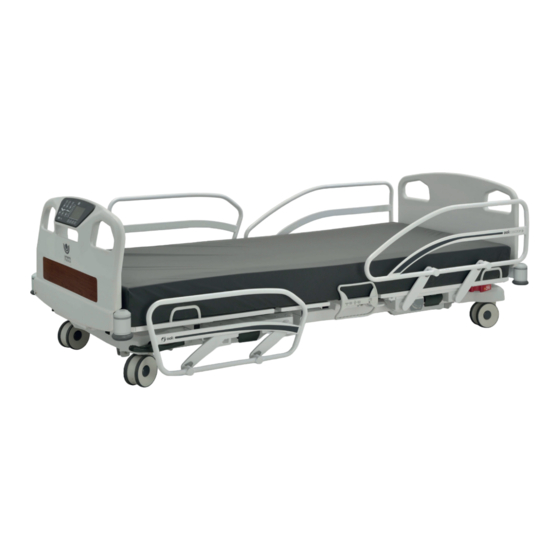
Page 8: Product Illustration
INTRODUCTION Product illustration Item Description Item Description Headboard Backrest section CPR release handle (optional) Patient control outlet (optional) Power cord Auxiliary power outlets (optional) Angle indicator (optional) Patient restraint location Drainage bag support (optional) Siderail release handle Brake, neutral and steer pedal Footboard Footboard control Control on frame (optional) -
Page 9: Technical Specifications
INTRODUCTION Technical specifications Weights and dimensions Bed weight (based on features) 336 lb to 369 lb 152 kg to 167 kg Safe working load (including patient, mattress and 500 lb 227 kg accessories) Maximum mattress weight 44 lb 20 kg Maximum accessories weight 100 lb 45 kg... - Page 10 INTRODUCTION Environmental conditions 50 °F to 104 °F 10 °C to 40 °C ambient temperature relative humidity 5 to 95% without condensation 5 to 95% without condensation 500 to 1060 hPa 500 to 1060 hPa atmospheric pressure Transport and storage -40 °F to 158 °F -40 °C to 70 °C ambient temperature...
-
Page 11: Emc Information
INTRODUCTION EMC information Guidance and manufacturer’s declaration - emission The “FL36 Medical Bed” is intended for use in the electromagnetic environment specified below. The customer or user of the “FL36 Medical Bed” should ensure that it is used in such an environment. Emission test Compliance Electromagnetic environment - guidance... - Page 12 INTRODUCTION Guidance and manufacturer’s declaration - immunity The “FL36 Medical Bed” is intended for use in the electromagnetic environment specified below. The customer or user of the “FL36 Medical Bed” should ensure that it is used in such an environment. Electromagnetic Immunity test IEC 60601 test level...
-
Page 13: Symbols And Definitions
INTRODUCTION Symbols and definitions Different symbols are used on the product and in this manual. Their purpose is to inform the user on functional details or on safety related measures. Indicates the need for the user to consult the instructions for use for Indicates the medical device cautionary information such as manufacturer... - Page 14 INTRODUCTION Indicates the need for the user to Indicates the need for the user to consult instructions for use follow instructions for use Indicates that the equipment has been independently tested and meets the Indicates a general mandatory action applicable published safety standard Indicates that when disposed, the equipment must be collected separately in accordance with the...
-
Page 15: Pictograms And Definitions
INTRODUCTION Pictograms and definitions Different pictograms are used on the product and in this manual. Their purpose is to facilitate the reading and the understanding of the different functionalities to the user. If bed is equipped with screen, additional pictograms may be displayed in different menus. - Page 16 INTRODUCTION Button for selection of bed exit Illustration with LED indicators for control degree of detection for active selection of tone Detection 1 - OUT-OF-BED Button for selection of bed exit Button for selection of audio control degree of detection for signal type Detection 2 - BED EXITING Illustration indicating selection of/...
- Page 17 INTRODUCTION Illustration indicating interdiction Illustration indicating patient is to drink liquids subject to confusion Illustration indicating that two Illustration indicating interdiction person are required to move the to change bed configuration patient Illustration indicating that no Illustration indicating the necessity to monitor blood pressure visitors are allowed USER MANUAL —...
-
Page 18: Safety Measures
INTRODUCTION Safety measures Terms DANGER, WARNING, ATTENTION and IMPORTANT are used in this manual to indicate important measures to take for use or maintenance of the equipment. The gradation, the definitions and safey measures shall be carefully reviewed and understood before use. Gradation and definition of safety measures DANGER Indicates an imminent hazardous situation, which if not avoided, will result in serious injury or death. - Page 19 INTRODUCTION WARNING • Grounding reliability can be achieved only when the bed is connected to a supply mains with protective ground or to a hospital grade outlet that is protectively grounded. • To avoid risk of electric shock hazard, bed must only be connected to a supply mains with protective ground or to a hospital grade outlet that is protectively grounded.
- Page 20 INTRODUCTION • If electrical equipment is connected to the auxiliary outlet or USB port, ensure that any electrical device introduced within the patient vicinity is not causing electrical interferences. The connected electrical equipment could results in power leads or radiation emitting devices closer to the patient (ex: computer charger, mobile phone) and their interference shall be managed to avoid biased diagnostics (ex: ECG monitors) or limited treatment efficiency (ex: pacemakers).
- Page 21 INTRODUCTION • The organization responsible for usage and for maintenance of a medical electrical system shall ensure that the equipments connected on the auxiliary power outlet are conforming to the electrical specifications like, but not limited to, power drawn, leakage currents or electromagnetic compliance for electromedical systems (IEC60601-1;...
-
Page 23: Getting Started
Bed must be properly installed and verified prior to be put in service. Refer to the list below to ensure proper set up. Steps list for set up 1. Perform a complete visual inspection of the bed. Contact Umano Medical or local representative if there are any damages or missing item. 2. To prevent permanent damages, ensure bed has reached... -
Page 24: Zeroing Procedures
GETTING STARTED 16. Install mattress with proper specifications. If applicable, ensure that mattress handles are placed under the mattress and do not interfere with siderails mechanism. 17. If bed is equipped with bed exit detection, perform a zero procedure on the bed after all equipment has been installed. -
Page 25: Operating Instructions
OPERATING INSTRUCTIONS IMPORTANT Read and understand all information covered in this manual before operating the equipment. Users shall be knowledgeable about inherent hazards related to use of electric beds. Power up and modes of operation If a power failure occurs, bed will automatically fall in sleep mode and initiate the battery-powered mode. If the bed operates on batteries, the patient control for bed-motion will remain functional. -
Page 26: System Signals And Messages
OPERATING INSTRUCTIONS System signals and messages The hospital bed FL36 can issue a signal or a message to inform the user that an action is required. It can be visual and/or audible and/or textual if bed is equipped of the display screen. Visual signal A visual signal may take the form of flashing LEDs on the membrane of the footboard for a bed equipped of a bed exit system. -
Page 27: Base, Frame And Litter
OPERATING INSTRUCTIONS BASE, FRAME AND LITTER IMPORTANT The bed is equipped with base covers at head and foot ends of the bed. Base covers must be kept in place while bed is in use to preserve electrical and mechanical components. Brake, neutral and steer Brake, neutral and steer can be activated manually with one of the 2 pedals located at foot end of the bed. -
Page 28: Motion Interrupt (Optional)
OPERATING INSTRUCTIONS Motion interrupt (optional) The bed can be equipped with a motion interrupt system that detects an obstruction under the bed when the bed elevation system is being lowered. The system will then interrupt the bed motion. If bed is equipped with a display screen on footboard using software version 2.0, a message will appear in the display screen to indicate that an obstruction has been detected. -
Page 29: Bumpers With Side View Lights (Optional)
OPERATING INSTRUCTIONS Bumpers with side view lights (optional) Bumpers with integrated side view light system are located at both foot end corners of the bed. Foot end bumpers offer a 3/4" socket to support IV poles. The green lights intensity can be controlled if the bed is equipped with display screen;... -
Page 30: Cpr Release (Optional)
OPERATING INSTRUCTIONS CPR release (optional) CPR release handles are located on each side of the bed frame, under the backrest section. Usage shall be limited to emergency situations only. An over usage could lead to mechanical degradation. Operation: 1. To activate, pull and hold the CPR release handle to flatten all sections of patient sleep surface. 2. -
Page 31: Auxiliary Power Outlets And Usb Port (Optional)
OPERATING INSTRUCTIONS Auxiliary power outlets and USB port (optional) Optionally, bed can be equipped with 120V auxiliary power outlets and USB port intended to be used as convenient power source for patient and caregiver use to energize low power devices. Power outlets are limited to 120V 5A/600W, with protective earth terminal. -
Page 32: Communication Port (Optional)
OPERATING INSTRUCTIONS Communication port (optional) Bed can be equipped of a USB communication port intended to be used for software updates and/or bed diagnosis. IMPORTANT The communication port will not be functional if bed is unplugged. This communication port shall not be used as a power source for portable devices. Control on frame (optional) An optional control located on the frame, at the foot end of the bed, offers complementary functions to... -
Page 33: Siderails And Patient Mobilization Helper
OPERATING INSTRUCTIONS SIDERAILS AND PATIENT MOBILIZATION HELPER Standard configuration offers head and foot end siderails. Optionally, the bed can be confirgured with head end siderails only. IMPORTANT Refer to the pictograms and definitions section (page 13) to support identification. WARNING •... -
Page 34: Patient Mobilization Helper (Optional)
OPERATING INSTRUCTIONS Patient mobilization helper (optional) Bed is equipped with patient mobilization helper which operates with a release handle located under the sleep surface. WARNING • Always ensure that patient is capable of proper usage of the patient mobilization helper. ATTENTION •... - Page 35 OPERATING INSTRUCTIONS Patient control 2 functions (optional) The UP/DOWN press buttons offer motion of backrest section form 0 degree to 60 degrees. The UP/DOWN press buttons offer motion of thigh and foot sections. Motion are simultaneous. To activate: 1. Press and hold button. 2.
-
Page 36: Headboard And Footboard
OPERATING INSTRUCTIONS HEADBOARD AND FOOTBOARD A choice of headboards and footboards is available in various materials which present different features to adapt to the customer’s needs and/or environment. Option of plastic boards or MDF boards is available. IMPORTANT Ensure there is no obstruction between the frame and the footboard connectors when installing the footboard. Transport handles/bars Headboard and footboard are both built to ease transportation. -
Page 37: Footboard Control
OPERATING INSTRUCTIONS Footboard control Footboard control is located on the board at the food end of the bed. Do not use sharp or small pointed objects on membranes to avoid permanent damages. Pictograms inform the user of positioning possibilities and features. IMPORTANT Refer to the pictograms and definitions... - Page 38 OPERATING INSTRUCTIONS Standard configuration Bed motion lockout to the footboard controls can be set with one of the 3 closed padlock pictogram press buttons with integrated LED. A solid amber LED ON indicates that bed motion illustrated below is locked in the patient control, the bed motions can still be activated from the footboard control panel.
- Page 39 OPERATING INSTRUCTIONS Bed exit control system The patient risk (or fall risk) management functionalities offer a volume range that can be set with the press button illustrated with the loudspeaker pictogram. The LED indicator by one of the 4 levels will indicate if volume is OFF, low, medium or high.
-
Page 40: Footboard Control With Display Screen
OPERATING INSTRUCTIONS Footboard control with display screen Blue buttons are associated with actions whereas grey buttons are not and cannot be selected in that specific Medsurg screen. Refer to the pictograms and definitions section November 1st 12:00 Auto (page 13) if required. The information section is 0 º... -
Page 41: Detailed Screen Functions (Sw 1.3)
OPERATING INSTRUCTIONS Detailed screen functions (SW 1.3) The following section details the screen functions for bed equipped with software version 1.3. The software version can be verified through Preference screen in Maintenance menu. USER MANUAL — 74-36103-ENG R6... - Page 42 OPERATING INSTRUCTIONS Home screen Screen informs the user of the height and the angulations of patient sleep surface. User can return to the Home screen menu at any time by pressing on the Home pictogram. IMPORTANT The bed height is rounded up. The angulations accuracy of backrest section is +/- 2 The angulations accuracy of Trendelenburg and reverse-Trendelenburg is +/- 2 A simplified interface displaying less options is offered for a simplified use.
- Page 43 OPERATING INSTRUCTIONS Fall risk management screen The Premium interface displays all bed options. The selected bed exit control level of detection will be highlighted. Select: • Detection 1 to change level of detection to a Fall risk management patient out-of-bed. Confirm by pressing YES to November 1st 12:00 set, press NO to return to Fall risk management...
- Page 44 OPERATING INSTRUCTIONS Alarm Settings screen The Alarm Settings menu offers a selection of 10 different tones and a range of 4 volume levels including mute. Select: • - or + to set volume level; a red “X” over the Alarm Settings loudspeaker indicates alarm is muted, 3 volume November 1st 12:00...
- Page 45 OPERATING INSTRUCTIONS Inform Settings screen The Inform Settings menu offers the possibility to set a screen saver with display of different pictograms from Pictograms library to inform caregivers of patient condition and predisposition to fall and/or display of required siderails configuration. The screen also offers the possibility to set a color coding with 1, 2 or 3 different colors. If one or more pictograms from the Pictograms library are selected, an Inform pictogram will display in the upper right corner of the display screen.
- Page 46 OPERATING INSTRUCTIONS • Color chart button to get to the Color codes Color codes Preview: screen, select 1, 2 or 3 colors, and to display November 1st 12:00 selected colors on the screen saver. Cancel • START to display the screen saver with Color codes selected settings.
- Page 47 OPERATING INSTRUCTIONS Date/time screen By default, the Date and Hour buttons are flashing and are pre-selected for editing. Select: • Cancel to cancel command and return to Date and time preference menu. November 1st 12:00 • UP/DOWN arrows to edit Day and/or Hours. •...
- Page 48 OPERATING INSTRUCTIONS Lock srceen. Total lockout activation also displays an orange padlock on the Preference box in the display screen to inform caregivers. Select: • Back Lock for activation of lockout for motion Lock of backrest section. November 1st 12:00 •...
- Page 49 OPERATING INSTRUCTIONS Languages screen Select: • Français to set French language menus. Preference Languages November 1st 12:00 • English to set English language menus. • Español to set Spanish language menus. English Français • Português to set Portuguese language menus. Español Português Languages...
-
Page 51: Detailed Screen Functions (Sw 2.0)
OPERATING INSTRUCTIONS Detailed screen functions (SW 2.0) The following section details the screen functions for bed equipped with software version 2.0. The software version can be verified through Preference screen in Maintenance menu. USER MANUAL — 74-36103-ENG R6... - Page 52 OPERATING INSTRUCTIONS Home screen Screen informs the user of the height and the angulations of patient sleep surface. User can return to the Home screen menu at any time by pressing on the Home pictogram. IMPORTANT The bed height is rounded up. The angulations accuracy of backrest section is +/- 2 The angulations accuracy of Trendelenburg and reverse-Trendelenburg is +/- 2 A simplified interface displaying less options is offered for a simplified use.
- Page 53 OPERATING INSTRUCTIONS Care Pause When the bed exit detection is armed, press the Disarm Detection button to apply a Care Pause and give the caregiver 5 minutes to provide any care to the patient without disactivating the bed exit system and without generating a bed exit detection alarm.
- Page 54 OPERATING INSTRUCTIONS Patient risk management screen The Premium interface displays all bed options. The selected bed exit control level of detection will be highlighted. Select: • Detection 1 to change level of detection to Patient risk management a patient out-of-bed. Confirm by pressing November 1st 12:00 YES to set, press NO to return to Patient risk...
- Page 55 OPERATING INSTRUCTIONS Alarm Settings screen The Alarm Settings menu offers a selection of 10 different tones and a range of 4 volume levels including mute. Select: • - or + to set volume level; a red “X” over the Alarm Settings loudspeaker indicates alarm is muted, 3 volume November 1st 12:00...
- Page 56 OPERATING INSTRUCTIONS Inform Settings screen The Inform Settings menu offers the possibility to set a screen saver with display of different pictograms from Pictograms library to inform caregivers of patient condition and predisposition to fall and/or display of required siderails configuration. The screen also offers the possibility to set a color coding with 1, 2 or 3 different colors. If one or more pictograms from the Pictograms library are selected, an Inform pictogram will display in the upper right corner of the display screen.
- Page 57 OPERATING INSTRUCTIONS • Color chart button to get to the Color codes Color codes Preview: screen, select 1, 2 or 3 colors, and to display November 1st 12:00 selected colors on the screen saver. Cancel • START to display the screen saver with selected settings.
- Page 58 OPERATING INSTRUCTIONS Date/time screen By default, the Date and Hour buttons are flashing and are pre-selected for editing. Select: • Cancel to cancel command and return to Date and time preference menu. November 1st 12:00 • UP/DOWN arrows to edit Day and/or Hours. •...
- Page 59 OPERATING INSTRUCTIONS Lock srceen. Total lockout activation also displays an orange padlock on the Preference box in the display screen to inform caregivers. Select: • Back Lock for activation of lockout for motion Lock of backrest section. November 1st 12:00 •...
- Page 60 OPERATING INSTRUCTIONS Languages screen Select: • Français to set French language menus. Preference Languages November 1st 12:00 • English to set English language menus. • Español to set Spanish language menus. English Français • Português to set Portuguese language menus. Español Português Languages...
- Page 61 OPERATING INSTRUCTIONS Zero screen A zero can be performed on the bed through the Zero screen, in the Patient risk management menu. Select: • Start to perform the zero on the bed. Ensure Zero the patient is not on the bed before performing November 1st 12:00 the zero.
-
Page 63: Accessories
ACCESSORIES WARNING • Always ensure precautions are taken when using compatible accessories in foot section accessory sockets. Foot section accessory sockets are attached to the moving part of the frame. If foot section requires to be actuated, accessory will follow the foot section angle and will be tilted or moved away from patient. Fixed IV pole 3/4"... -
Page 64: Folding Iv Pole 3/4" Diameter - Fa64507
ACCESSORIES Folding IV pole 3/4" diameter - FA64507 The folding IV pole FA64507 is equipped of 2 hanging hooks. Each hanging hook has a capacity of 11 lb/5 kg for a total maximum safe working load of 22 lb/10 kg. ATTENTION •... -
Page 65: 1" Fixed Iv Pole For 3/4" Socket - Fa64522
ACCESSORIES 1" fixed IV pole for 3/4" socket - FA64522 The fixed IV pole FA64522 is equipped of 2 hanging hooks. Each hanging hook has a capacity of 20 lb/9 kg for a total maximum safe working load of 40 lb/18 kg. ATTENTION •... -
Page 66: Fixed Iv Pole 1" For 1" Socket - Fa64508
ACCESSORIES Fixed IV pole 1" for 1" socket - FA64508 The fixed IV pole FA64508 is equipped of 2 hanging hooks. Each hanging hook has a capacity of 20 lb/9 kg for a total maximum safe working load of 40 lb/18 kg. ATTENTION •... -
Page 67: Left 1" Folding Iv Pole For 1" Socket - Fa64521
ACCESSORIES Left 1" folding IV pole for 1" socket - FA64521 The folding IV pole FA64521 is equipped of 2 hanging hooks. Each hanging hook has a capacity of 15 lb/6.8 kg for a total maximum safe working load of 30 lb/13.6 kg. The left 1" folding IV pole FA64521 can be combined to the right 1"... -
Page 68: Right 1" Folding Iv Pole For 1" Socket - Fa64523
ACCESSORIES Right 1" folding IV pole for 1" socket - FA64523 The folding IV pole FA64523 is equipped of 2 hanging hooks. Each hanging hook has a capacity of 15 lb/6.8 kg for a total maximum safe working load of 30 lb/13.6 kg. The right 1" folding IV pole FA64523 can be combined to the left 1"... -
Page 69: Removable Pump Holder - Fa64513
ACCESSORIES Removable pump holder - FA64513 The removable pump holder FA64513 is intended to be installed on the footboard to support pumps. It has a maximum safe load capacity of 70 lb/31 kg ATTENTION • Remove accessory when not in use. Installation and removal 1. -
Page 70: Oxygen Bottle Holder - Fa64505
ACCESSORIES Oxygen bottle holder - FA64505 The vertical oxygen bottle holder is designed to support an oxygen bottle. It can be installed at the bed head end; it has a maximum safe load capacity of 35 lb/16 kg. Installation and operation 1. -
Page 71: Patient Helper - Fa64504
ACCESSORIES Patient helper - FA64504 The patient helper is intended to provide support to the patient for repositioning when in bed. It is not designed to support patient when getting in or out the bed. The maximum load capacity of the patient helper is 170 lb/77 kg. WARNING •... -
Page 72: Removable Patient Control 2 Functions - Fa64509
ACCESSORIES Removable patient control 2 functions - FA64509 The two functions patient control is intended to allow patient or healthcare professionnals to adjust the backrest section and foot section of the bed. Pictograms inform the user of positioning possibilities and features. Do not use sharp or small pointed objects on membranes to avoid permanent damages. -
Page 73: Removable Patient Control 5 Functions - Fa64510
ACCESSORIES Removable patient control 5 functions - FA64510 IMPORTANT If the bed is configured without controls on footboard, the patient control is not the same. The control is then necessary to activate the bed’s functions and will be used as unique bed control. The plugging is done differently; refer to the maintenance department for the replacement of the control. -
Page 75: Preventive Maintenance
PREVENTIVE MAINTENANCE A preventive maintenance is required annually for this equipment. This maintenance program is based on a normal use. Preventive maintenance frequency shall be increased if required. A minimum of one (1) annual verification of all items of the Preventive maintenance annual checklist (page 74) is recommended. -
Page 76: Preventive Maintenance Annual Checklist
PREVENTIVE MAINTENANCE Preventive maintenance annual checklist Use copy of this sheet for your records. Note if adjustment or repair were required. Keep on file. Serial Number and Location : Date of preventive maintenance: Preventive maintenance perfomed by: ̉ Overall condition ̉... -
Page 77: Cleaning
CLEANING A potential of electric shock hazard exists with a power supplied bed. Ensure to unplug power cord of power outlet before cleaning. Do not put water or solution directly in or on connectors. If applicable, secure any bed section that would have to be lifted during cleaning procedures. -
Page 79: Warranty
Umano Medical, found to be defective. In addition, Umano Medical warrants for life to the original purchaser that the welds on its products will be free from structural defects. -
Page 80: Index
INDEX Angle indicator Headboard Siderail 31 Auxiliary power outlet 6, 8, 21, IV pole 5, 61, 62, 63, 64, 65, Backrest 7, 21, 28, 33, 36, 40, Battery Motion interrupt 58 Bed exit 5, 23, 27, 28, 37, 41, Motion lockout 36 Brake, neutral and steer 25 Bumper Nightlight... - Page 81 U m a n o M e d i c a l I n c . 2 3 0 b o u l e v a r d N i l u s - L e c l e r c L’...
Need help?
Do you have a question about the ook cocoon and is the answer not in the manual?
Questions and answers