Umano Medical ook snow FL36 User Manual
Hide thumbs
Also See for ook snow FL36:
- User manual (77 pages) ,
- User manual (81 pages) ,
- User manual (98 pages)
Table of Contents
Advertisement
Advertisement
Table of Contents

Subscribe to Our Youtube Channel
Related Manuals for Umano Medical ook snow FL36


Summary of Contents for Umano Medical ook snow FL36
- Page 1 FL36 FL36-SC User manual 2 0 2 2 / 0 3 | 7 4 - 3 6 1 2 1 - E N G R 2...
- Page 3 FL36 FL36-SC User manual 2 0 2 2 / 0 3 | 7 4 - 3 6 1 2 1 - E N G R 2...
- Page 4 Copyright 2022 Umano Medical Inc. All Rights Reserved. No part of this publication may be reproduced, distributed, or transmitted in any form or by any means, including photocopying, recording, or using electronic or mechanical methods, without the prior written permission of the publisher, except in the case of brief quotations embodied in critical reviews and certain other noncommercial uses permitted by copyright law.
-
Page 5: Table Of Contents
TABLE OF CONTENTS INTRODUCTION Accessory socket caps (optional) ....32 ........5 Covered restraint points (optional) ..32 Product description ........5 Motion key lock (optional) ......32 Product intended use ........5 Patient restraint location ......33 Contact ............6 Bumpers ..........34 Bumpers with side view lights Application environments and (optional) ..........34 limitations .............7... - Page 6 TABLE OF CONTENTS SMART SCREEN DISPLAY ....49 ACCESSORIES .........69 Mattress extension for bed extender - DM64505 and DM64506 .......70 Siderail pads - DM64515 and DM64516 ..71 Fixed IV pole 3/4" diameter - FA64506 ..73 Folding IV pole 3/4" diameter - FA64507 ..74 1"...
-
Page 7: Introduction
INTRODUCTION This manual includes instructions and information that are necessary for a normal and secure use of the ook<snow>> bed designed for mental health environment, model FL36 and FL36-SC. Reading and understanding of instructions and information included in this manual, or other documents supplied with the product, are required prior to usage, or prior to perform maintenance on the equipment. -
Page 8: Contact
The user and/or patient should report any suspected serious incident related to the device by informing the manufacturer and the competent authority of the member state in which the serious incident has occurred. Umano Medical Inc. 230 boulevard Nilus-Leclerc, L’Islet QC G0R 2C0 CANADA... -
Page 9: Application Environments And Limitations
INTRODUCTION Application environments and limitations Application environments Description ook<snow>> Intensive/critical care provided in a hospital where 24 h medical supervision and constant monitoring is required and provision of life support system/equipment Applicable* used in medical procedures is essential to maintain or improve the vital functions of the patient. -
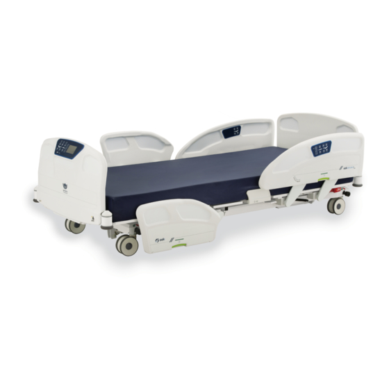
Page 10: Product Illustration
INTRODUCTION Product illustration Item Description Item Description Headboard Backrest section CPR release handle (optional) Nurse call plug (optional) Power cord Siderail control Angle indicator Brake, neutral and steer pedal Drainage bag support Siderail release handle Patient siderail control Footboard Footboard control Bumper Frame control (optional) Bed extender handle (optional) -
Page 11: Technical Specifications
INTRODUCTION Technical specifications Weights and dimensions Bed weight (based on features) 303 lb to 438 lb 137 kg to 199 kg Safe working load (including patient, mattress and 600 lb 272 kg accessories) Maximum mattress weight 44 lb 20 kg Maximum accessories weight 100 lb 45 kg... - Page 12 INTRODUCTION Environmental conditions 50 °F to 104 °F 10 °C to 40 °C ambient temperature 5 to 95% without 5 to 95% without relative humidity condensation condensation atmospheric pressure 500 to 1060 hPa 500 to 1060 hPa Transport and storage ambient temperature -40 °F to 158 °F -40 °C to 70 °C...
-
Page 13: Emc Information
INTRODUCTION EMC information Guidance and manufacturer’s declaration - emission The “FL36 Medical Bed” is intended for use in the electromagnetic environment specified below. The customer or user of the “FL36 Medical Bed” should ensure that it is used in such an environment. Emission test Compliance Electromagnetic environment - guidance... - Page 14 INTRODUCTION Guidance and manufacturer’s declaration - immunity The “FL36 Medical Bed” is intended for use in the electromagnetic environment specified below. The customer or user of the “FL36 Medical Bed” should ensure that it is used in such an environment. Electromagnetic Immunity test IEC 60601 test level...
-
Page 15: Symbols And Definitions
INTRODUCTION Symbols and definitions Different symbols are used on the product and in this manual. Their purpose is to inform the user on functional details or on safety related measures. Indicates the need for the user to consult the instructions for use for Indicates the medical device cautionary information such as manufacturer... - Page 16 INTRODUCTION Indicates the patient maximum weight Indicates the total maximum charge for a safe use of the equipment for a safe use of equipment Indicates the need for the user to Indicates the need for the user to consult instructions for use follow instructions for use Indicates that the equipment has been Indicates a general mandatory action...
-
Page 17: Pictograms And Definitions
INTRODUCTION Pictograms and definitions Different pictograms are used on the product and in this manual. Their purpose is to facilitate the reading and the understanding of the different functionalities to the user. If bed is equipped with screen, additional pictograms may be displayed in different menus. - Page 18 INTRODUCTION Button with LED indicator for Illustration indicating location of activation/deactivation, of bed exit auxiliary outlets control system 5A 120V 60Hz Button for selection of bed exit Illustration indicating group of control degree of detection for buttons for bed exit control system Detection 1 - OUT-OF-BED settings Button for selection of bed exit...
- Page 19 INTRODUCTION Illustration indicating that patient Illustration indicating the necessity has one or more allergies to monitor blood pressure Illustration indicating that patient Illustration indicating necessity to is subject to pressure ulcers monitor blood sugar level Illustration indicating patient is Illustration indicating interdiction subject to confusion to drink liquids Illustration indicating that two...
- Page 20 INTRODUCTION Illustration indicating that the bed Illustration indicating that the bed is connected to the connectivity is connected to internet by cable application Illustration indicating that the bed Illustration indicating that the is disconnected from the internet bed is disconnected from the connection by cable connectivity application Illustration indicating that the bed...
-
Page 21: Safety Measures
INTRODUCTION Safety measures Terms DANGER, WARNING, ATTENTION and IMPORTANT are used in this manual to indicate important measures to take for use or maintenance of the equipment. The gradation, the definitions and safey measures shall be carefully reviewed and understood before use. Gradation and definition of safety measures DANGER Indicates an imminent hazardous situation, which if not avoided, will result in serious injury or death. - Page 22 INTRODUCTION WARNING • Grounding reliability can be achieved only when the bed is connected to a supply mains with protective ground or to a hospital grade outlet that is protectively grounded. • To avoid risk of electric shock hazard, bed must only be connected to a supply mains with protective ground or to a hospital grade outlet that is protectively grounded.
- Page 23 INTRODUCTION • If electrical equipment is connected to the auxiliary outlet or USB port, ensure that any electrical device introduced within the patient vicinity is not causing electrical interferences. The connected electrical equipment could result in power leads or radiation emitting devices closer to the patient (e.g. computer charger, mobile phone) and their interference shall be managed to avoid biased diagnostics (e.g.
- Page 24 INTRODUCTION • Connecting electrical equipment to the auxiliary outlet (optional) effectively leads to creating a medical electrical system, and can result in a reduced level of safety. • Always ensure proper product clearance in order to reach all the different device controls, boards, accessories and electrical connections.
-
Page 25: Getting Started
Bed must be properly installed and verified prior to be put in service. Refer to the list below to ensure proper set up. Steps list for set up 1. Perform a complete visual inspection of the bed. Contact Umano Medical or local representative if there are any damages or missing items. -
Page 26: Zeroing Procedures
GETTING STARTED 17. If applicable, test the room lights functions for proper operation. 18. If applicable, verify following options for proper operation: bed extender, auxiliary power outlets and USB port, nightlights, etc. 19. If bed is equipped with bed exit detection, perform a zero procedure on the bed after all equipment has been installed. - Page 27 GETTING STARTED Zeroing procedure for a bed with display screen with bed exit only Procedure: 1. Bed is electrically powered up. Ensure sleep surface is completely flat, siderails are raised, and put the bed elevation system at intended height of use. Apply the brakes. 2.
-
Page 28: Configuration Steps For Server Connection Settings (Optional)
IMPORTANT Only Umano Medical representatives are authorized to perform a system update with an approved software. Umano Medical takes no responsibility for malicious activity that may result from lack of current, appropriate IT security practices. The network administrator must follow the steps and enter the proper configuration information. -
Page 29: Operating Instructions
OPERATING INSTRUCTIONS IMPORTANT Read and understand all information covered in this manual before operating the equipment. Users shall be knowledgeable about inherent hazards related to use of electric beds. Power up and modes of operation If a power failure occurs, bed will automatically fall in sleep mode and initiate the battery-powered mode. If the bed operates on batteries, the patient and caregiver controls for bed-motion will remain functional. - Page 30 OPERATING INSTRUCTIONS Battery powered mode: Battery powered mode is activated if power failure occurs or if the bed power cord is unplugged from wall outlet ; it will first fall in sleep mode. Under the battery- powered mode, an armed bed exit control system will send a signal to the nurse call communication system to inform of battery-powered mode;...
-
Page 31: System Signals And Messages
OPERATING INSTRUCTIONS System signals and messages The hospital bed FL36 can issue a signal or a message to inform the user that an action is required. It can be visual and/or audible and/or textual if the bed is equipped of the display screen. Visual sign A visual signal may take the form of flashing LEDs on the membrane of the footboard for a bed equipped of a bed exit system. -
Page 32: Base, Frame And Litter
OPERATING INSTRUCTIONS BASE, FRAME AND LITTER The bed for mental care environments can be configured with casters and braking system, or with the option of a floor mount. IMPORTANT The bed is equipped with base covers at head and foot ends of the bed. Base covers must be kept in place while bed is in use to preserve electrical and mechanical components. -
Page 33: Floor Mount (Optional)
OPERATING INSTRUCTIONS Floor mount (optional) The bed with floor mount offers the option of a bed without casters. It also offers the possibility to fix the bed to the floor. To move the bed from one location to another, refer to the Transporting bed section (page 29). -
Page 34: Accessory And Equipment Sockets
OPERATING INSTRUCTIONS Accessory and equipment sockets WARNING • Always ensure precautions are taken when using compatible accessories in the foot section accessory sockets. The foot section accessory sockets are attached to the moving part of the frame. If that section needs to be actuated, the accessories will follow the foot section angle and will be tilted or moved away from patient. -
Page 35: Patient Restraint Location
If not avoided, situation could result in patient injury. Umano Medical does not issue any recommandations regarding the requirements and/or the physical restraints used with patient, with any of its products. -
Page 36: Bumpers
OPERATING INSTRUCTIONS Bumpers Bumpers are located at each corner of bed to preserve wall. Each bumper offers a 3/4" socket to support IV poles. Two optional bumpers are situated at head end of the bed for additional protection of the walls. Bumpers with side view lights (optional) Bumpers with integrated side view light system are located at both foot end corners of the bed. -
Page 37: Cpr Release (Optional)
OPERATING INSTRUCTIONS CPR release (optional) CPR release handles are located on each side of the bed frame, under the backrest section. Usage shall be limited to emergency situations only. An over usage could lead to mechanical degradation. Operation: 1. To activate, pull and hold the CPR release handle to flatten all sections of patient sleep surface. If siderail is in lower position, ensure to slightly raise the siderail before activating the CPR release handle. -
Page 38: Nightlight (Optional)
OPERATING INSTRUCTIONS Nightlight (optional) Two nightlights are located on each side of the bed frame, under the seat section, to illuminate the floor area where the patient will get in or out of the bed. Light intensity can be controlled if the bed is equipped with display screen; refer to the footboard control section (page 45). -
Page 39: Connectors, Ports And Outlets
OPERATING INSTRUCTIONS CONNECTORS, PORTS AND OUTLETS The bed can be equipped with different types of connectors, ports and outlets. Refer to the Product illustration (page 8) for localization. Nurse call connector (optional) If the bed is equipped with the optional nurse call system, the connector selected when ordered will be located at the head end of the bed, on the frame. -
Page 40: Auxiliary Power Outlets And Usb Port (Optional)
OPERATING INSTRUCTIONS Auxiliary power outlets and USB port (optional) Optionally, bed can be equipped with 120V or 230V auxiliary power outlets and USB port intended to be used as convenient power source for patient and caregiver use to energize low power devices. Power outlets are limited to 600VA (5A to 120V or 2A to 230V), with protective earth terminal. -
Page 41: Head And Foot Ends Siderails
OPERATING INSTRUCTIONS HEAD AND FOOT ENDS SIDERAILS The bed is equipped with a set of head and foot end siderails. Options of patient mobilization helper or bed without siderails are also available. If bed is configured without siderails, some features and accessories won’t be available and bed is subject to limitations of application environments;... -
Page 42: Patient Mobilization Helper (Optional)
OPERATING INSTRUCTIONS Lower a foot or head end siderail: 1. Grasp the upper center of the rail; with second hand, pull the handle up and rotate downward. 2. Siderail will be below the mattress surface. The handle will display a green window for an unlocked but safe status. WARNING •... -
Page 43: Patient Siderail Controls
OPERATING INSTRUCTIONS Patient siderail controls Patient siderail controls are located on the inside of each head siderail. Do not use sharp or small pointed objects on membranes to avoid permanent damages. Pictograms inform the user of positioning possibilities and features. ATTENTION •... -
Page 44: Caregiver Siderail Controls
OPERATING INSTRUCTIONS Another patient control configuration offers, in addition to the optional features, a press button for control of the room lights. Depending on the configuration, the light bulb button can offer the possibility to turn ON or OFF the backlight option or the reading light option. QDF36-2920 OPTIONAL FEATURES ILLUSTRATED To use optional feature:... -
Page 45: Patient Control (Optional)
OPERATING INSTRUCTIONS Another caregiver siderail control membrane is offered with 5 functions: the UP/DOWN press buttons for motion of backrest section, motion of thigh and foot sections simultaneously, motion of elevation system, chair position and flat surface, with the LED indicator to indicate that the bed is power supplied. -
Page 46: Headboard And Footboard
OPERATING INSTRUCTIONS HEADBOARD AND FOOTBOARD Bed is equipped with a set of headboard and footboard. If patient’s medical condition requires to prevent tampering and abusive uses, and does not require intensive, critical or acute care, the headboard and footboard can be permanently attached to the frame and can help avoid inappropriate intentional or unintentional usage by the patient towards the environment, or towards oneself or others. -
Page 47: Footboard Control
OPERATING INSTRUCTIONS Footboard control Footboard control is located on the board at the food end of the bed. Do not use sharp or small pointed objects on membranes to avoid permanent damages. Pictograms inform the user of positioning possibilities and features. IMPORTANT Refer to the pictograms and definitions... - Page 48 OPERATING INSTRUCTIONS Standard configuration Bed motion lockout to the siderails controls can be set with one of the 3 closed padlock pictogram press buttons with integrated LED. A solid amber LED ON indicates that bed motion illustrated below is locked in the siderails, the bed motions can still be activated from the footboard control panel.
- Page 49 OPERATING INSTRUCTIONS Bed exit control system The patient risk management functionalities offer a volume range that can be set with the press button illustrated with the loudspeaker pictogram. The LED indicator by one of the 4 levels will indicate if volume is OFF, low, medium or high.
-
Page 50: Footboard Control With Display Screen
OPERATING INSTRUCTIONS Footboard control with display screen Blue buttons are associated with actions whereas grey buttons are not and cannot be selected in that specific screen. Refer to the pictograms and definitions section Medsurg Medsurg November 1st November 1st 12:00 12:00 Auto (page 15) if required. -
Page 51: Smart Screen Display
SMART SCREEN DISPLAY SMART SCREEN DISPLAY [ Images in the following section represent the 3.0 software display; display may vary according to the software version of the bed. ] USER MANUAL — 74-36121-ENG R2... - Page 52 SMART SCREEN DISPLAY Home screen Screen informs the user of the height and the angulations of patient sleep surface. User can return to the Home screen menu at any time by pressing on the Home pictogram. IMPORTANT The bed height is rounded up. The angulations accuracy of backrest section is +/- 2 The angulations accuracy of Trendelenburg and reverse-Trendelenburg is +/- 2 A simplified interface displaying less options is offered for a simplified use.
- Page 53 SMART SCREEN DISPLAY Home screen with integrated scale (optional) The functions Arm (Disarm), Auto Arm, Patient Risk management and Preference of a bed configurated with the scale option operate as detailed in the Home screen section (page 50). Refer to this section if needed. IMPORTANT The bed height is rounded up.
- Page 54 SMART SCREEN DISPLAY Care Pause When the bed exit detection is armed, press the Disarm Detection button to apply a Care Pause and give the caregiver 5 minutes to provide any care to the patient without disactivating the bed exit system and without generating a bed exit detection audible sign.
- Page 55 SMART SCREEN DISPLAY Patient risk management screen The Premium interface displays all bed options. The selected bed exit control level of detection will be highlighted. WARNING • The bed exit detection system must be used with patients with minimum weight of 50 lb/22.6 kg and the auto-arm function must be used with patient with minimum weight of 70 lb/31.8 kg.
- Page 56 SMART SCREEN DISPLAY Patient risk management screen for bed with scale (optional) The Premium interface displays all bed options. The Patient Risk Management selected bed exit control level of detection will be November 1st I 12:00 highlighted. The functions Bed exit, Inform, View Log and bed status management of a bed configurated with the scale option operate as detailed in the Patient...
- Page 57 SMART SCREEN DISPLAY Bed exit management screen Select: • Detection 1 to change level of detection to Bed Exit Management a patient out-of-bed. Confirm by pressing November 1st I 12:00 YES to set, press NO to return to Patient risk management screen.
- Page 58 SMART SCREEN DISPLAY Bed status management screen (optional) The bed status management menu offers the possibility to set the brakes, siderails, brackrest and/or elevation system position for bed status monitoring. The menu also includes the activation and deactivation of the monitoring and the possibility to set the audible signal’s volume and tone.
- Page 59 SMART SCREEN DISPLAY Inform Settings screen The Inform Settings menu offers the possibility to set a screen saver with display of different pictograms from Pictograms library to inform caregivers of patient condition and predisposition to fall and/or display of required siderails configuration.
- Page 60 SMART SCREEN DISPLAY • Color chart button to get to the Color codes Color codes screen, select 1, 2 or 3 colors, and to display November 1st I 12:00 selected colors on the screen saver. Preview: Select Color • Turn Reminder to activate a patient turn reminder notification.
- Page 61 SMART SCREEN DISPLAY Advanced settings The Advanced settings menu offers the possibility to Advanced Settings edit the settings for the date/time, the languages, the November 1st I 12:00 units and the password. Select: Password Units • The desired settings to edit. Date/Time Languages •...
- Page 62 SMART SCREEN DISPLAY Lights configuration screen (optional) Select: • Cancel to cancel command and return to Lights configuration preference menu. November 1st I 12:00 • UP arrow to set screen, nightlights or sideview Screen Nightlights Sideview lights intensity up to completely OFF illustrated Lights with red X.
- Page 63 SMART SCREEN DISPLAY New patient screen The New patient menu offers the possibility to edit the patient information to either reset or save the different settings. Select: • Edit to select the information to save. Once New Patient selected, the button’s background will turn November 1st I 12:00 green.
- Page 64 SMART SCREEN DISPLAY Lock screen The Lock screen offers activation of a total lockout for motion of backrest section, knee gatch and/or Hi-Lo. Total lockout activation also displays an orange padlock on the Preference box in the display screen to inform caregivers. Select: •...
- Page 65 SMART SCREEN DISPLAY Maintenance screen The maintenance menu offers access to different Home functionalities (errors log, load cell values, calibration, factory settings, software version, interface settings, Always ensure wifi configuration, network information and web Auto Arm Raise left foot siderail proper bed address).
- Page 66 SMART SCREEN DISPLAY Motion interrupt (optional) The motion interrupt system offers the possibility to interrupt a downward motion from the bed elevation system when an obstacle is found under the bed. If applicable, a message will appear in the display screen to indicate that an obstruction has been detected.
- Page 67 SMART SCREEN DISPLAY Scale screen For proper use of scale related features, ensure bed is not interfering with any item of the environment or in contact with wall. Do not touch bed. ATTENTION • A zeroing procedure must be performed each time new accessories are installed or removed from the bed, or each time a new patient is admitted in the bed.
- Page 68 SMART SCREEN DISPLAY Weight Log screen The Weight Log screen informs of patient logged Weight Log weight and records up to 20 entries. Use arrows to November 1st I 12:00 navigate and read from oldest to most recent entry. Possibility to erase Weight Log entries by pressing Weight / Lb ERASE and confirm intention to erase by pressing YES, or cancel command by pressing NO.
- Page 69 SMART SCREEN DISPLAY Undo Zero screen The Undo Zero screen offers the caregiver the possibility to return to a previous zero in the event a zero is mistakenly performed. The last 4 zeros are recorded with the date on which they were performed and can be selected.
-
Page 71: Accessories
ACCESSORIES WARNING • Always ensure precautions are taken when using compatible accessories in the foot section accessory sockets. The foot section accessory sockets are attached to the moving part of the frame. If that section needs to be actuated, the accessories will follow the foot section angle and will be tilted or moved away from patient. -
Page 72: Mattress Extension For Bed Extender - Dm64505 And Dm64506
ACCESSORIES Mattress extension for bed extender - DM64505 and DM64506 Cushions DM64505 and DM64506 can be used with the optional bed extender to make sleep surface longer. IMPORTANT Remove patient from surface before extending the bed and installing cushion. Mattress extension DM64505 (35" x 10" x 6") Use DM64505 in conjunction with a mattress of 80”... -
Page 73: Siderail Pads - Dm64515 And Dm64516
ACCESSORIES Siderail pads - DM64515 and DM64516 Siderail pads DM64515 and DM64516 can be used on the siderails to add protection for the patient or to help avoid inappropriate intentional or unintentional usage by the patient towards oneself. Siderail pads cannot be used if bed is configured without siderails. - Page 74 ACCESSORIES Mobilisation helper pads - DM64516 Use DM64516 when bed is equipped with patient mobilisation helper. Installation and operation: 1. Properly lock the siderails controls. Refer to the Standard configuration in the Headboard and footboard section (page 46). 2. Completely raise the head end siderails. 3.
-
Page 75: Fixed Iv Pole 3/4" Diameter - Fa64506
ACCESSORIES Fixed IV pole 3/4" diameter - FA64506 The fixed IV pole FA64506 is equipped of 2 hanging hooks. Each hanging hook has a capacity of 11 lb/5 kg for a total maximum safe working load of 22 lb/10 kg. ATTENTION •... -
Page 76: Folding Iv Pole 3/4" Diameter - Fa64507
ACCESSORIES Folding IV pole 3/4" diameter - FA64507 The folding IV pole FA64507 is equipped of 2 hanging hooks. Each hanging hook has a capacity of 11 lb/5 kg for a total maximum safe working load of 22 lb/10 kg. ATTENTION •... -
Page 77: 1" Fixed Iv Pole For 3/4" Socket - Fa64522
ACCESSORIES 1" fixed IV pole for 3/4" socket - FA64522 The fixed IV pole FA64522 is equipped of 2 hanging hooks. Each hanging hook has a capacity of 20 lb/9 kg for a total maximum safe working load of 40 lb/18 kg. ATTENTION •... -
Page 78: 1" Fixed Iv Pole For 1" Socket - Fa64508
ACCESSORIES 1" fixed IV pole for 1" socket - FA64508 The fixed IV pole FA64508 is equipped of 2 hanging hooks. Each hanging hook has a capacity of 20 lb/9 kg for a total maximum safe working load of 40 lb/18 kg. ATTENTION •... -
Page 79: Left 1" Folding Iv Pole For 1" Socket - Fa64521
ACCESSORIES Left 1" folding IV pole for 1" socket - FA64521 The folding IV pole FA64521 is equipped of 2 hanging hooks. Each hanging hook has a capacity of 15 lb/6.8 kg for a total maximum safe working load of 30 lb/13.6 kg. The left folding IV pole FA64521 can be combined to the right folding IV pole FA64523 for additional hooks. -
Page 80: Right 1" Folding Iv Pole For 1" Socket - Fa64523
ACCESSORIES Right 1" folding IV pole for 1" socket - FA64523 The folding IV pole FA64523 is equipped of 2 hanging hooks. Each hanging hook has a capacity of 15 lb/6.8 kg for a total maximum safe working load of 30 lb/13.6 kg. The left folding IV pole FA64521 can be combined to the right folding IV pole FA64523 for additional hooks. -
Page 81: 1/2" Iv Pole Adapter - Fa64514
ACCESSORIES 1/2" IV pole adapter - FA64514 The 1/2" IV pole adapter FA64514 is 15" long with a diameter of 1" and can be installed in one of the 3/4" accessory sockets of the bed. It is designed to hold an IV pole with a 1/2" diameter. It has a maximum safe working load of 40 lb/18 kg. -
Page 82: Oxygen Bottle Holder - Fa64505
ACCESSORIES Oxygen bottle holder - FA64505 The vertical oxygen bottle holder is designed to support an oxygen bottle. It can be installed at the bed head end; it has a maximum safe load capacity of 35 lb/16 kg. Installation and operation 1. -
Page 83: Oxygen Bottle Holder With Clamp - Fa64527
ACCESSORIES Oxygen bottle holder with clamp - FA64527 The oxygen bottle holder with clamp is designed to hold an oxygen bottle. It can be installed at the head end of the bed, in the corner bumpers sockets. The clamp situated on the oxygen bottle holder is designed to hold on a pole of 3/4"... -
Page 84: Patient Helper - Fa64504
ACCESSORIES Patient helper - FA64504 The patient helper is intended to provide support to the patient for repositioning when in bed. It is not designed to support patient when getting in or out of bed. The maximum load capacity of the patient helper is 170 lb/77 kg. WARNING •... -
Page 85: Preventive Maintenance
PREVENTIVE MAINTENANCE A preventive maintenance is required annually for this equipment. This maintenance program is based on a normal use. Preventive maintenance frequency shall be increased if required. A minimum of one (1) annual verification of all items of the Preventive maintenance annual checklist (page 84) is recommended. -
Page 86: Preventive Maintenance Annual Checklist
PREVENTIVE MAINTENANCE Preventive maintenance annual checklist Use copy of this sheet for your records. Note if adjustment or repair were required. Keep on file. Serial Number and Location : Date of preventive maintenance: Preventive maintenance perfomed by: ̉ Overall condition ̉... -
Page 87: Cleaning
CLEANING WARNING • A potential of electric shock hazard exists with a power supplied bed. Ensure to unplug power cord of power outlet before cleaning. Do not put water or solution directly in or on connectors. If applicable, secure any bed section that would have to be lifted during cleaning procedures. This bed and compatible accessories are not designed to be steam cleaned, hosed off or ultrasonically cleaned. -
Page 89: Warranty
Umano Medical, found to be defective. In addition, Umano Medical warrants for life to the original purchaser that the welds on its products will be free from structural defects. -
Page 90: Index
INDEX Frame control 8 Angle indicator 8 Zeroing 66 Headboard Auxiliary power outlet 8, 10, 24, IV pole 73, 74, 75, 76, 77, Backlight 15 Backrest 9, 23, 35, 41, 42, 43, 46, 50, 51, Mattress extension Bed exit 28, 34, 37, 47, 53, Motion lockout 46 Bed extender 8 Brake, neutral and steer... - Page 91 Emergo Consulting (UK) Limited c/o Cr360 - UL International Compass House, Vision Park Histon Cambridge CB24 9BZ United Kingdom U m a n o M e d i c a l I n c . EMERGO EUROPE 2 3 0 b o u l e v a r d N i l u s - L e c l e r c Prinsessegracht 20 2514 AP The Hague L’...
Need help?
Do you have a question about the ook snow FL36 and is the answer not in the manual?
Questions and answers