
Subscribe to Our Youtube Channel
Related Manuals for Fromm P380


Summary of Contents for Fromm P380
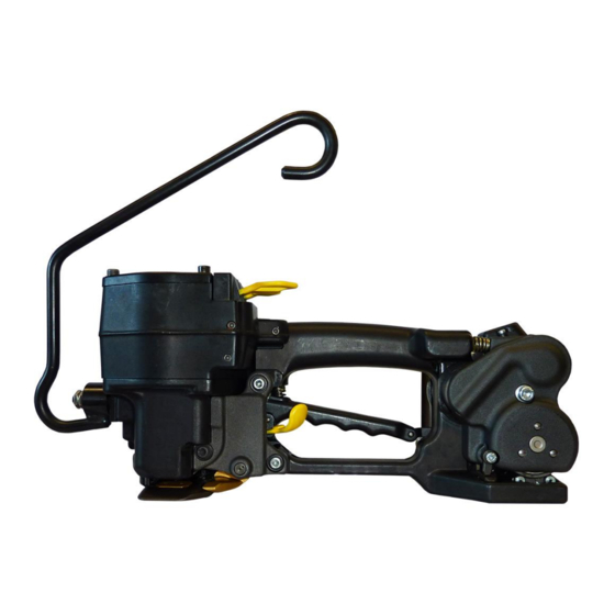
- Page 1 SERVICE MANUAL PNEUMATIC PLASTIC STRAPPING TOOL MODEL P380 Manual for authorized dealers and service points...
-
Page 2: Table Of Contents
INDEX PAGE TECHNICAL DETAILS 1.1.1 Air supply ........... . 1-3 1.1.2 Pneumatic schematic . -
Page 3: Technical Details
Only trained and instructed personnel is authorized to perform servicing and maintenance works! 1.1 TECHNICAL DETAILS 1.1.1 Air supply Main air line min. 2" Air line min. 1/2" Shut off valve Pressure adjustment valve with Manometer Air unit G3/8 Air hose Shut off valve max. -
Page 4: Pneumatic Schematic
1.1.2 Pneumatic schematic Tensioner valve Tension force control valve Tensioning motor Exhaust silencer Welding valve Throttle 0.6 Welding motor valve Welding time valve Welding motor 10 Cooling time valve 11 Welding cylinder 12 Welding signal valve 13 Turn off valve 14 Cooling signal valve 15 Welding turn off valve 16 Cylinder reverse stop... -
Page 5: Details Of The Pneumatic Control System
• At the same time the Turn off valve (13) is driven by compressed air from the left side, switches and thus is blocking the air connection to the Tensioner valve (1). Also the upper piston surface of the welding cylinder (11) and the cylinder reverse stop (16) is ventilated. Both cylinders extend.The straps between welding gripper and welding stop gripper are compressed. - Page 6 7 Welding motor valve 6 Throttle 0.6 5 Welding valve 12 Welding signal valve 15 Welding turn off valve b Valve lever for welding 14 Cool down 1 Tensioner valve signal valve a Valve lever for tensioning 13 Turn off valve 10 Cool down time valve 8 Welding time valve...
-
Page 7: Conversion Parts
1.2 CONVERSION PARTS When converting strap thickness or strap width the following parts must be exchanged: Tool Item-No. 49.3801 49.3802 49.3811 49.3812 49.3821 Strap dimension 13mm x 13mm x 15mm x 15mm x 16mm x 0.40-0.64 0.65-1.05 0.40-0.64 0.65-1.05 0.40-0.64 Tensioning wheel P35.3202 P35.3203... -
Page 8: Periodic Maintenance And Control
Tightness of the pneumatic system • Strap guidance • Strap take up and strap tensioning • Tensioning force adjustment minimal and maximal (see operation manual P380) • Cutting of the upper strap • Welding time adjustment (see operation manual P380) •... -
Page 9: Troubleshooting
1.3.2 Troubleshooting A sufficient compressed air supply and the use of the tool’s specific strap should be guaranteed before each tool repair. SYMPTOM CAUSE REMEDY Tool doesn’t tension, The tensioning wheel is packed with Clean tensioning wheel with Tensioning motor runs strap residue or is worn and mills on compressed air or replace it the strap... -
Page 10: Checklist
Insertion of the strap • Strap guidance • Strap take up and strap tension • Tension force adjustment minimal and maximal (see operation manual P380) • Cutting of the upper strap • Welding time adjustment (see operation manual P380) •...
Need help?
Do you have a question about the P380 and is the answer not in the manual?
Questions and answers