
Related Manuals for Fromm P380


Summary of Contents for Fromm P380
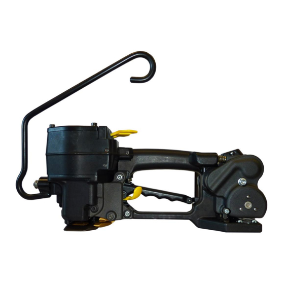
- Page 1 SERVICE MANUAL PNEUMATIC PLASTIC STRAPPING TOOL MODEL P380 Manual for authorized dealers and service points...
- Page 2 1.2 CONVERSION PARTS When converting strap thickness or strap width the following parts must be exchanged: Tool Item-No. 49.3801 49.3802 49.3811 49.3812 49.3821 Strap dimension 13mm x 13mm x 15mm x 15mm x 16mm x 0.40-0.64 0.65-1.05 0.40-0.64 0.65-1.05 0.40-0.64 Tensioning wheel P35.3202 P35.3203...
-
Page 3: Glueing Rules
1.3.4 Glueing rules Following parts have to be glued with LOCTITE 603: N2.2145 Planet shaft P35.3103 with the parallel pins N2.2145. P35.3103 P38.1141 Gearing cover P38.1141 with parallel pins N21.2101 N21.2101 The screws N1.2112 have to be glued additionally in the planetary gear stage P35.0130 using LOCTITE 222. -
Page 4: Lubrication Rules
1.3.5 Lubrication rules P38.1199 • Lubricate the rocker P38.1125 and the bolt P38.1201 in the area of the welding jaw with Klüber Isoflex NBU 15. • Lubricate the balls N3.1702, ball cage P38.1199 and the 15 X N3.1702 running surface of the balls on the welding gripper with Klüber Isoflex Alltime SL2. - Page 5 Vane: If the minimum diameters (see drawing) are not reached anymore, the vanes P35.2024 or P35.3108 must be exchanged. P35.3138 P35.2021 P35.3108 P35.2024 min. 43.2 mm min. 37.2 mm Assembling of the cover P35.3105 on the idler step P35.0130 Observe assembling direction of the cover. The division of the holes is not 3x120°.
- Page 6 Exchange of strap guides and strap stop Disassembling: • For protection of the tooth system from the gripper a piece of plastic strap should be inserted before loosing or tightening the base plate. (therefore lift the handle) • Unscrew base plate •...
- Page 7 Picture 2 P38.1160/62/64/66 N11.1116 P38.1105 Thrustpiece in swivel in position P38.1111 P38.1110 Adjustment of the strap guide after service or repair work If the strap guides P38.1160/62/64/66 and P38.1161/63/65/67 don't touch the base plate or after the welding you see pressure points at the side of the upper strap you have to adjust the strap guides: - Disconnect the tool from the air supply.
-
Page 8: Recommended Spare Parts
Assembling of the valve P38.0103 Pay attention to the assembling position of the spring ring N2.1613. The grinded side must show to the outside. outside grinded outside grinded N2.1613 N2.1613 1.4 RECOMMENDED SPARE PARTS Following spare parts are recommended for stock keeping: Item-No. -
Page 9: Accessory Tools
1.5 ACCESSORY TOOLS Item number Description Application N71.3247 Press in and press out pressure pad N3.1157/P35.3103 N71.3264 Press in and press out arbor N3.1157/P35.3103 N71.3237 Press in and press out arbor N3.1159/P32.1037 and N3.2356/P38.1147 N71.3238 Press in and press out pressure pad N3.1159/P32.1037 N71.3235 Press in and press out arbor... - Page 10 1.5.1Use of accessory tools Accessory tools should only be used with the suitable arbor press N7.5108 N7.5108 in order to avoid a tilt of the pressed in parts. Additional a retainer (N7.3215) is necessary. N7.3215 Part Disassembly Assembly N3.1157/ P35.3103 N71.3264 N3.1157 P35.3103...
- Page 11 Part Disassembly Assembly N3.4509/ N71.3235 P38.1140 N3.4509* P38.1140 N72.3203 *Assembling position see „Assembly information“ P32.1023/ N3.1134/ N71.3243 N71.3244 P32.1732 P32.1732 N3.1134 N71.3245 P32.1023 N3.2347/ N71.3239 P38.1125 N71.3240 N3.2347 P38.1125 The seal of the N71.3241 needle bushing (N3.2347) has to face to the outside.
- Page 12 Part Disassembly Assembly N3.2356/ P38.1147 N71.3266 N71.3237 N3.2356 P38.1147 N71.3245 P32.1023/ Picture 1 N71.3244 P35.0140 N71.3254 N71.3280 P32.1023 N71.3255 P35.0140 Picture 2 N71.3281 1-20...
- Page 13 Part Disassembly Assembly P35.2023/ N3.1174/ P35.3138 resp. Commercially P35.2021 available Puller. The distance between rotor (P35.3138 resp. P35.2021) and end plate (P35.2023) should be 0.03 mm N71.3277 P35.3138 P35.2021 P35.2023 N3.1174 N71.3276 1-21...
- Page 14 Proceeding for valve disassembling: • Press clip together and insert it into the hole, until it snaps into the shown position • Insert coupler pull out exhaust ring Attention! When disassembling the valves don’t damage the ball seat. Part Disassembly P35.2005 Coupler resp.
- Page 15 Part Disassembly P35.3157/ P35.3157 P38.1112 N71.3274 Hook in here P35.3145/ P38.1112 P35.3145 N71.3274 Hook in here 1-23...
- Page 16 Part Disassembly P35.2059/ P38.1112 Hook in here N71.3274 P35.2059 P35.3114/ N71.3299 P35.3114 P38.1112 Hook in here 1-24...
- Page 17 Exchange of thrust pieces P38.1104 Disassembling: Required tools: punch Ø max. 2.8mm, spring clamp N72.3201 and arbour press - Press down the spring bolt P38.1103 through the bore of the thrust piece P38.1104. - Push the spring clamp N72.3201 between thrust piece P38.1104 and spring bolt P38.1103. Attention! Disassembling and assembling of the bolt N2.2112 has only to be made from the side which is shown in picture 2.
- Page 18 P38.0116/17 1 P35.2073 N1.5105 P38.1202 P38.1101 P38.0115 1 N1.7116 P35.2069 1 P38.1135 P35.2068 P38.1148 1 N2.5623 P35.2067 N2.2138 N6.6212 1 P38.1136 P38.1149 N1.2110 N2.4906 N21.5204 P38.0118 P38.1131 N1.1808 N2.2110 1 P38.1132 N1.7111 N21.5205 P38.1170/72 P38.1151 P38.1133 N21.5206 N21.2119 N21.2102 N2.2166 P38.1154/56/57 P35.1207 N1.6407...
- Page 19 N1.1140 P38.0101 N1.6228 P38.1106 N1.2159 N2.4409 1 N2.5199 N2.2124 N1.6199 P38.0116/17 P38.1108 (N6.3503) N2.4409 1 P38.1107 P38.1203 N2.5199 1 P38.1111 P38.1108 1 P38.1110 (N6.3511) P38.1107 1 P38.1109 N2.2112 N21.5201 P38.1105 P38.0106 P38.1102 N1.6115 N1.6405 N21.5206 N1.1807 N11.1116 1 N21.5201 P38.1103 P38.1168/69 P38.1104 N2.2402...
- Page 20 1 N3.1702 1 P38.1205 N1.3128 2 P32.1123 1 N3.1702 P38.0110 P38.0116/17 N3.1174 P35.2038 P38.1137 N2.3368 N2.2402 1 N6.6224 N1.6237 3 5x P35.2022 N1.1306 3 5x P35.2024 1 N6.6262 3 5x P35.2022 P35.2020 P35.2021 N2.2402 N11.1147 P35.2023 N3.1174 P38.0111 1 N6.6237 1 N2.5259 P35.2027 N2.2163...
- Page 21 N1.1820 5 P38.1117 N11.1147 P35.3136 5 P38.1116 N1.6237 1 Mobilux EP2 N11.1171 2 Molykote BR 2 plus N11.1171 3 Mobil Velocite No.6 P38.0116/17 4 Klüber Isoflex Alltime SL2 1 P35.3133 5 Klüber Isoflex NBU 15 1 P35.3131 P38.0102 6 Loctite 603 1 N2.5152 7 Loctite 222 1 N6.6280...
- Page 22 SPARE PARTS LIST P380 3.1 Type independent spare parts P380.0001.01 Item-No. in group Pcs. Description Dimension Field N11.1116 P38.0101 1 SCREW M4 X 12 N11.1119 P38.0116/17 2 SCREW M5 X 20 N11.1143 P38.0116/17 1 SCREW M6 X 20 N11.1147 P38.0112...
- Page 23 Item-No. in group Pcs. Description Dimension Field N2.1121 P38.0116/17 2 SECURITY RING N2.1301 P38.0105 1 CIRCLIP N2.1610 P38.0112 1 SPRING RING SB44 N2.1613 P38.0103 2 SPRING RING D23+ N2.2102 P38.0102 2 PARALLEL PIN 5 m6 X 16 N2.2102 P38.0106 2 PARALLEL PIN 5 m6 X 16 N2.2110 P38.0109...
- Page 24 Description Dimension Field N41.9127 1 ADHESIVE LABEL 20 X 10 X 0.1 N41.9129 1 ADHESIVE LABEL p max. 6 bar/87 psi N43.9179 1 TYPE PLATE <<P380>> N44.9104 P38.0116/17 1 ADHESIVE LABEL <<FROMM>> N4.1221 P38.0119 1 BUFFER N4.9159 1 LABEL <<CE>>...
- Page 25 Item-No. in group Pcs. Description Dimension Field [P35.0133] P38.0112 1 GEAR WHEEL [P35.0137] P38.0106 1 GEAR WHEEL [P35.0140] P38.0106 1 MOTOR CELL P35.1207 P38.0116/17 1 INSERT P35.2005 P38.0102 1 EXHAUST RING P35.2020 P38.0110 1 JACKET P35.2021 P38.0110 1 ROTOR P35.2022 P35.0140 10 FELT C11+...
- Page 26 Item-No. in group Pcs. Description Dimension Field P35.3145 P38.0102 1 SUSTAINING RING P35.3146 P38.0102 1 PUSHER P35.3149 P38.0104 1 END RING P35.3150 P38.0104 1 INTERMEDIATE RING P35.3151 P38.0104 1 SUSTAINING RING P35.3152 P38.0104 1 PUSHER P35.3153 P38.0104 1 SUSTAINING RING P35.3155 P38.0102 1 PUSHER...
- Page 27 Item-No. in group Pcs. Description Dimension Field P38.1127 P38.0106 1 COVER P38.1128 P38.0106 1 COVERING P38.1129 P38.0106 1 EXHAUST SILENCER P38.1129 P38.0112 1 EXHAUST SILENCER P38.1130 P38.0106 1 SIEVE P38.1130 P38.0112 1 SIEVE P38.1131 P38.0109 1 HANDLE P38.1132 P38.0109 1 THRUST PIECE P38.1133 P38.0109 1 SEESAW LEVER...
- Page 28 3.2 Type dependent spare parts P380.0001.01 Type 49.3801.01 49.3801.01 P380/13/0.40-0.64 P380.0001.01 21.06.10 Item-No. in group Pcs. Description Dimension Field P35.3202 P38.0116 1 TENSIONING WHEEL [P38.0116] 1 BASE MODEL P38.1154 1 STRAP STOP P38.1158 1 STRAP GUIDE P38.1160 1 STRAP GUIDE P38.1161...
- Page 29 Type 49.3812.01 49.3812.01 P380/15/0.65-1.05 P380.0001.01 21.06.10 Item-No. in group Pcs. Description Dimension Field P35.3203 P38.0117 1 TENSIONING WHEEL [P38.0117] 1 BASE MODEL P38.1156 1 STRAP STOP P38.1158 1 STRAP GUIDE P38.1162 1 STRAP GUIDE P38.1163 1 STRAP GUIDE P38.1169 P38.0117 1 CUTTER [P38.1172]...
- Page 30 Type 49.3831.01 49.3831.01 P380/19/0.40-0.64 P380.0001.01 21.06.10 Item-No. in group Pcs. Description Dimension Field P35.3202 P38.0116 1 TENSIONING WHEEL [P38.0116] 1 BASE MODEL P38.1157 1 STRAP STOP P38.1159 1 STRAP GUIDE P38.1166 1 STRAP GUIDE P38.1167 1 STRAP GUIDE P38.1168 P38.0116 1 CUTTER [P38.1170]...
- Page 31 OPERATION MANUAL PNEUMATIC PLASTIC STRAPPING TOOL MODEL P380...
- Page 32 For the usage of the tool on packages with sensitive surface there can two plastic plates be P38.1206 assembled to the bottom side of the tool. N1.2227 Every plate including fixation screws can be ordered with item number P38.0120 or P38.1204 P38.0121(see drawing) respectively. N1.2223 P38.0120 P380.0001.01.enT1.fm...
-
Page 33: Exchange Of Wearing Parts
The direction of rotation of the tensioning wheel is marked at the front of the tensioning wheel . • The parallel pin N21.2102 must be inserted in the guide of the strap guide lever P38.1150 when assembling the end cover. P380.0001.01.enT1.fm 4-11... - Page 34 Lubricate the rocker and the bolt P38.1201 in the area of the welding jaw with Klüber Isoflex NBU 15. • Lubricate the balls, ball cage and the running surface of the balls on the welding gripper with Klüber Isoflex Alltime SL2. P380.0001.01.e 4-12...
- Page 35 Base plate N1.6237 N1.6503 N11.1119 N1.6407 Mobilux EP2 N1.1168 N1.1306 Loctite 222 Assembling in opposite order. Assembly advise • Pay attention to the assembling position of the cutter (see drawing). • Glue the screws N1.1306 with Loctite 222. 4-13 P380.0001.01.enT1.fm...
Need help?
Do you have a question about the P380 and is the answer not in the manual?
Questions and answers