
Subscribe to Our Youtube Channel
Related Manuals for Sierra BioTrak 645i


Summary of Contents for Sierra BioTrak 645i
- Page 1 Thermal Mass Flow Meter for Wastewater Processes Instruction Manual Document: S-IM-645i/745i Rev C_PN 109637 831.373.0200 | 5 Harris Court Building L, Monterey, CA 93940 | sierrainstruments.com...
- Page 3 TRADEMARKS BioTrak™, BioCal™, BioSelect™, FlowTrak™, BioView™ and DigiSense™ are trademarks of Sierra Instruments, Inc. Other product and company names listed in this manual are trademarks or trade names of their respective manufacturers. Disclaimer | 3...
- Page 4 BioTrak 645i/745i Disclaimer Warnings and Cautions General Safety Information We use caution and warning statements throughout this book to draw your attention to important information. Symbol Key Symbol Symbol Meaning Description This statement appears with information that is important to protect people and equipment from Warning damage.
- Page 5 BioTrak 645i/745i Disclaimer CAUTION • Caution! Before making adjustments to the 645i/745i, verify the flow meter is not actively monitoring or reporting to any master control system. Adjustments to the electronics will cause direct changes to flow control settings. • Caution! All flow meter connections, isolation valves and fittings for hot tapping must have the same or higher pressure rating as the main pipeline.
- Page 6 If the problem persists, contact Sierra Instruments by e-mail (see inside front cover). For urgent phone support you may call (831) 373-0200 between 8:00 a.m. and 5:00 p.m. PST. In Europe, contact Sierra Instruments Europe at +31 72 5071400. In the Asia-Pacific region, contact Sierra Instruments Asia at +8621 5879 8521.
-
Page 7: Table Of Contents
BioTrak 645i/745i Table of Contents 1. Introduction p. 11-21 a. Quick Start Guide ............... . . p. 9 b. - Page 8 BioTrak 645i/745i Table of Contents 6. Maintenance p. 87-96 a. Safe Removal of Meter from Retractor ............p. 89 b.
-
Page 9: Quick Start Guide
BioTrak 645i/745i Quick Start Guide Use the table below as a guide while using the worksheet on the next page to record your notes. NOTE! Please read the entire quick-start procedure before beginning installation. Record inside diameter (ID). Ensure the actual pipe ID matches the pipe ID shown on the factory calibration OUTER certificate. - Page 10 Confirm the correct gas is selected for your application in theBioSelect™ menu Your Notes: If you are experiencing any problems after completing this procedure, please call the Sierra Instruments Service Department at 831-373-0200 to review this information. Quick Start Guide | 10...
-
Page 11: Introduction
BioTrak BioTrak 645i/745i 645i/745i Introduction Fig. 1.1: 645i/745i Menu Tree - Main Menu Enter menu by scolling to display 4 and entering the password MAIN MENU I/O FLO DSP EXIT Display Menu, p. 15 Flow Menu 1, p. 13 I/O MENU I/O COM 420 EXIT Digital Output Menu, p. 12 SET 4‐20 mA Analog Outputs CH1 CH2 EXIT Communication mA=Temp Comm=Modbus Temp None Flow Modbus... - Page 12 BioTrak BioTrak 645i/745i 645i/745i Introduction Fig. 1.2: 645i/745i Menu Tree - Digital Outputs and Input MAIN MENU I/O FLO DSP EXIT I/O MENU I/O COM 420 EXIT Set I/O OUT INP EXIT OUT= Pulse Inp= Not Used Not used Not used Pulse Tot Reset HiFloAlm...
- Page 13 BioTrak BioTrak 645i/745i 645i/745i Introduction Fig. 1.3: 645i/745i Menu Tree - Flow Menu 1 MAIN MENU I/O FLO DSP EXIT FLOW MENU 1 DGN UNT FM2 EXIT Flow Menu 2 Menu, p. 14 DIAGNOSTIC SCFM FLO UNT=SCFM SCFH SIM BioCal EXIT NXT OK NM3/H NM3/M KG/H KG/M KG/S TMP UNT=° F Deg F LBS/H Simulate Flow? Deg C NXT ...
- Page 14 BioTrak BioTrak 645i/745i 645i/745i Introduction Fig. 1.4: 645i/745i Menu Tree - Flow Menu 2 MAIN MENU I/O FLO DSP EXIT FLOW MENU 1 DGN UNT FM2 EXIT FLOW MENU 2 GAS SPC PRM EXIT Parameters Level 2 Flow cutoff in selected units K fact = 0% Cutoff=12.5 SCFM CHG OK CHG OK BioSelect Menu, p. 17 ® Pipe_id=4.026 In RESTORE DATABASE? Pipe id in inches or mm YES NO CHG OK Filter=0.8 Sec RESET CRC?
- Page 15 BioTrak BioTrak 645i/745i 645i/745i Introduction Fig. 1.5: 645i/745i Menu Tree - Display Menu MAIN MENU I/O FLO DSP EXIT DISPLAY/PASSWORD DSP PSW EXIT Display 1 Line 1 FLo rate DSP1L1=FLo rate PASSWD=1234 Total NXT OK CHG OK Elps Display 1 Temp Line 2 Alarm FLo rate DSP1L2=Total Total NXT OK Elps Display 2 Temp Line 1 Alarm...
- Page 16 BioTrak BioTrak 645i/745i 645i/745i Introduction Fig. 1.6: 645i/745i Menu Tree - BioCal™ Menu MAIN MENU I/O FLO DSP EXIT FLOW MENU 1 DGN UNT FM2 EXIT DIAGNOSTIC MENU SIM BioCal EXIT BioCal MENU VER EXIT VERIFY BioCal? YES NO Choosing “Hold Value” will retain the last flow value while test is being performed. Hold Value Flo: Hold Value Go to zero NXT EXIT OK Take Control off‐line EXIT OK Verifying BioCal Please Wait Verifying BioCal 0.512 T=123 Displays a number value ...
- Page 17 BioTrak BioTrak 645i/745i 645i/745i Introduction Fig. 1.7: 645i/745i Menu Tree - BioSelect™ Menu MAIN MENU I/O FLO DSP EXIT FLOW MENU 1 DGN UNT FM2 EXIT FLOW MENU 2 Methane GAS PRM EXIT Digester Gas GAS=Methane GAS=Digester Gas Be sure mixture equals 100%. Methane NXT OK NXT OK Methane = 65.5 % UP DN OK Only for Digester Gas mix CO2 = 25.5 % UP DN OK Gas Mix (100%) Err: Mix=(110%) OK OK Shows only if no error is ...
- Page 18 BioTrak BioTrak 645i/745i 645i/745i Introduction Fig. 1.8: 645i/745i Menu Tree - Engineering Screens Press F1 and F2 at the same time to enter the Engineering Screens Press F4 to return to normal mode Press F1 to navigate up ENG Screens Press F2 to navigate down ENG1 ENG2 EXIT...
- Page 19 Therefore a device measuring mass flow is independent of temperature and pressure changes. The BioTrak 645i/745i provides a direct measurement of gas flow in Mass units (kg/hr, lb/hr), standard units (SCFM, SLPM) or normal units (NM3/hr, NLPM) with no additional temperature or pressure measurements required.
- Page 20 Flow Calibration Every Sierra Instruments flow meter is set to the customer's configuration at the factory using an App ID which is generated by the on-line configurator. The App ID specifies the gas type, flow range, serial communication and other settings in the meter.
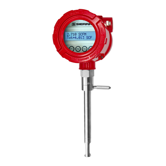
- Page 21 BioTrak BioTrak 645i/745i 645i/745i Introduction 645i/745i Functional Diagram An on-board 2 line x 16 character backlit LCD display shows flow rate, total flow, elapsed time, process gas temperature, and alarms. The display is also used in conjunction with the Configuration Panel for field configuration of flow meter settings such as gas selection, 4-20mA scaling, pulse output scaling, pipe area, flow cutoff, flow filtering, display configurations, diagnostics, communication parameters, and alarm limits.
-
Page 22: General
645i/745i Installation Installation Scope This section describes how to install the Sierra Instruments Model 645i/745i Flow Meter: For 645i Insertion Types: 1. Determine lateral position on the pipe 2. If moisture or condensation may be present in the gas, consider the radial orientation of the probe. -
Page 23: Lateral Placement
BioTrak 645i/745i Installation Instructions for Flow Meter Lateral Placement Install the Model 645i/745i flow meter so that it is far enough away from bends in the pipe, obstructions, or changes in line sizes to ensure a consistent flow profile. See Fig. 2.1 below for your meter type. - Page 24 The radial position of the meter may help reduce collection of moisture on the sensor. Condensing liquids contacting the meter's sensing elements will disrupt accurate flow measurement. Sierra Instruments recommends the flow meter be used in dry gas conditions whenever possible for highest accuracy.
-
Page 25: Welding Branch Outlet
BioTrak 645i/745i Installation Welding Branch Fitting to Pipe The probe of the 645i/745i must be installed perpendicular to the pipe to measure flow accurately. Use the following steps to ensure that the branch fitting is correctly welded to the pipe. Directions: 1. -
Page 26: Installation Depth
BioTrak 645i/745i Installation Installation Depth The installation depth of the sensor in the pipe is dependent on the pipe size. To get the most accurate reading, proper placement of the sensor window within the pipe is necessary. As shown in Fig 2.5, the end of the sensor window should be 0.73" (18.5 mm) past the center line of the pipe. Review the dimensional drawing below with the following equation to calculate insertion depth: L+D/2 + .73"... - Page 27 BioTrak 645i/745i Installation Mounting Instructions - Compression Fittings (645i Only) The 645i is mounted through a 0.781" hole and a female NPT branch outlet in the customer's pipe. Insertion style flow meters are not designed for use in pipes smaller than 1½". •...
-
Page 28: Mounting Instructions
BioTrak 645i/745i Installation Mounting Instructions - Compression Fittings (Inline and Insertion Meters Previously Installed) In cases where a compression fitting has already been swaged in an inline flow body or an insertion meter, use the following procedure. • Carefully insert the probe with swaged ferrules into the fitting until the front ferrule seats against the fitting (see Figure 2.7). -
Page 29: Orientation
Installation Rotating the Enclosure The BioTrak 645i/745i enclosure has been designed to allow the enclosure to rotate for optimal viewing of the display. To rotate the enclosure, first loosen the two set screws near the Flow Direction Indicator. Then rotate the enclosure into the desired position and tighten the set screws. - Page 30 BioTrak 645i/745i Installation Changing the Orientation of the 645i/745i Display The display can be rotated in 90° increments for optimum viewing of the screen. First, open the enclosure by unscrewing the enclosure cap and loosen the two captive screws to open the display assembly.
-
Page 31: Retractor Installation
BioTrak 645i/745i Installation Installation of a New Retractor Assembly 1. Remove collar clamp from probe using a 3/16" Hex Key. 2. Remove meter probe from retractor assembly and leave the ball valve open. Keep the collar spacer on the probe so it is not misplaced. 3. - Page 32 BioTrak 645i/745i Installation 4. Carefully slide the probe through the retractor assembly and through the hole to see if there is interference by touching the pipe wall with the end of the probe on the far side or until the probe cannot go deeper.
- Page 33 BioTrak 645i/745i Installation 5. Using the equation (L + D/2 + 0.73") from Figure 2.12, calculate the insertion depth and mark on the probe while measuring from the end of the probe. 6. The Retractor Clearance table of Figure 2.12 lists the space required to remove the meter from the retractor.
- Page 34 BioTrak 645i/745i Installation 7. Insert probe back into the retractor to the depth mark and hand-tighten the compression fitting. Make sure collar spacer is in place on the probe. 8. Verify that flow direction indicator is in line with pipe and in the direction of flow. Fig.
-
Page 35: Wiring (Electrical)
BioTrak 645i/745i Wiring Wiring Instructions To wire the 645i/745i connect the power and signal wires to the terminal blocks according to the labeling and instructions on the following pages. Fig. 3.1: 645i/745i Wiring Access Front Enclosure Cap Rear Enclosure Cap Unscrew front enclosure cap to access the Unscrew the rear enclosure cap to access display, configuration panel, and remote sensor... - Page 36 BioTrak 645i/745i Wiring Wiring Precautions WARNING! - DO NOT OPEN THE ENCLOSURE WHEN ENERGIZED OR AN EXPLOSIVE ATMOSPHERE IS PRESENT. • Connect earth ground to a chassis ground screw on the inside of 645i/745i enclosure. • All plumbing and electrical installations of flow meters must be in compliance with local codes, the end user’s best engineering practices, and manufacturer’s recommendations.
-
Page 37: Input Power
BioTrak 645i/745i Wiring Power Input Requirements: 12 to 24VDC External DC power supply must provide 12 to 24VDC (10 to 30VDC full input power range) at 6 Watts minimum. With 12VDC power, the 645i/745i can use up to 500mA. With 24VDC power, the 645i/745i can use up to 250mA. - Page 38 BioTrak 645i/745i Wiring Power Input Requirements: 100 to 240VAC If the 645i/745i has the AC power supply option, the AC power must provide 100 to 240VAC at 7 Watts minimum. Connect the power wiring to terminals TS1 pins 1 and 2 as shown in the diagram below. The enclosure must be properly grounded with a quality earth ground.
-
Page 39: Signal Wiring And Hart Communication Option
BioTrak 645i/745i Wiring 4-20mA Output and HART Communication Wiring: Customer-Supplied Power Source (Recommended) Bring the wiring in through either conduit hub. Connect the 4-20mA flow rate, 4-20mA temperature, and HART communication option wiring as shown in the diagram below. Fig. 3.4: 4-20mA Output Wiring for Isolated Customer-Supplied Power Source 645i/745i Customer PLC or DCS +12 to 24VDC... - Page 40 BioTrak 645i/745i Wiring 4-20mA Output and HART Communication Wiring: Loop Power Provided by 645i/745i (12 to 24VDC power option only) Bring the wiring in through either conduit hub. Connect the 4-20mA flow rate, 4-20mA temperature, and HART communication option wiring as shown in the diagram below. Fig.
-
Page 41: Pulse/Alarm Wiring (Optional Feature)
BioTrak 645i/745i Wiring Pulse/Alarm Output Wiring: Customer Supplied Power Source (Recommended) Bring Pulse/Alarm wiring in through either conduit hub. Connect the pulse/alarm wiring as shown in the diagram below. The pulse/alarm output is an open collector circuit capable of sinking a maximum of 20mA of current. - Page 42 BioTrak 645i/745i Wiring Pulse/Alarm Output Wiring: Power Provided by 645i/745i (12 to 24 VDC power option only) Bring Pulse/Alarm wiring in through either conduit hub. Connect the pulse/alarm wiring as shown in the diagram below. The pulse/alarm output is an open collector circuit capable of sinking a maximum of 20mA of current.
- Page 43 BioTrak 645i/745i Wiring Switch Input Wiring A remote switch can be used to reset the Totalizer and elapsed time, if enabled in the programming settings. Connect the switch input wiring as shown in the diagram below. Fig. 3.8: Switch Input Wiring Customer PLC or DCS 645i/745i 0.75A...
-
Page 44: Rs485 Wiring
BioTrak 645i/745i Wiring RS485 Wiring for Modbus RTU Wiring connections are made as shown in the diagram below for Modbus communication. Termination Resistor Connect a termination resistor across the receive/transmit signals of the last device on the communication line. To connect the 121 ohm termination resistor on the 645i/745i, set jumper W1 to the TERM position. -
Page 45: Hart Handheld Wiring
BioTrak 645i/745i Wiring HART 4-20mA Output Wiring: Handheld Communicator The 4-20mA current loop and HART modem connections are shown on p. 39 and p. 40. A handheld HART communicator can be connected to test points TP1 (+) and TP2 (-) with clip leads or to the 4-20mA terminal block. -
Page 46: Remote Wiring
BioTrak 645i/745i Wiring Remote Wiring Remote wiring is only necessary when the remote sensor option has been ordered. Fig. 3.11: Remote Wiring Remote Wiring 3 X Port, Remote Cable 3/4 " NPT Female 18 Gauge, 8 Conductor, Shielded, 100ft (30.48m) Max. Use an extension cable to connect the 645i/745i remote sensor to the electronics enclosure. - Page 47 Remote Wiring Terminals are accessed by opening the front display panel Cable Shield Detail Remote Wiring Terminal Located inside J-Box hinged cover panel Remote Wiring Terminal Remote Enclosure Customer Wires Sensor Wires Probe Sensor Wired By Sierra Wiring | 47...
- Page 48 Blue Green Blue Yellow Yellow Yellow Yellow Orange Yellow No Connection Shield NOTE! Wire colors listed here represent the wire colors of cables supplied by Sierra Instruments. Colors may vary if customer is supplying their own cable. Wiring | 48...
-
Page 49: Operation (Standard Operation)
The USB interface is a standard feature which allows communication with a PC to monitor readings and configure settings. BioView Software, is a free application program from Sierra Instruments that connects to the USB interface and allows data monitoring, configuration setting, and data logging to Excel. - Page 50 BioTrak 645i/745i Operation Measurement Mode Display Screens In the measurement mode, there are four different display screens (Display 1, 2, 3 and a prompt screen to enter the programming mode). Two display screens are user programmable (refer to Display Setup p. 57). Scrolling through the display is accomplished by pressing the F1 or F2 key to view the next or previous screen.
-
Page 51: Programming
BioTrak 645i/745i Operation Programming: Data Entry using the Display and Configuration Panel There are two basic types of menu entries: one for changing value or string and one for selecting from a selection list. To Change a Value or String : VALUE = 0.91234 Press CHG (F1) key to change the value, OK (F4) to accept the value. - Page 52 BioTrak 645i/745i Operation If the wrong password is entered, the message “Wrong Password” will display and then return to the programming entry screen. Main Menu If the password is accepted, the "Main Menu" screen will be shown: MAIN MENU EXIT This is the "Main Menu"...
- Page 53 BioTrak 645i/745i Operation 4 mA = 0 SCFM Enter the value for the 4mA and press OK (F4). NOTE! When the flow rate exceeds the programmed value for the 20mA set point, the analog output will stay at 20mA and an alarm code will be generated. NOTE! 4mA is normally set to 0.
- Page 54 BioTrak 645i/745i Operation Pulse/Alarm Output The Pulse/Alarm feature can be accessed from the "Main Menu," press I/O (F1). EXIT Press OUT (F1) to select the pulse output. The following screen will show: OUT = Pulse Press NEXT (F1) to cycle through output options until you have the selection for "OUT=Pulse" and press OK (F4).
- Page 55 BioTrak 645i/745i Operation Entering data in Unit per Pulse: From the Pulse/alarm Output Menu, press U/P (F2) and the following screen will show: UNT/PLS = 0.5 Press CHG (F1) to change the setting and then OK (F4) to accept entry. The value entered is in unit per pulse (i.e.
- Page 56 BioTrak 645i/745i Operation OUT = HiFloAlm Then press NXT (F1) to select the correct alarm and press OK (F4). Selections are: Not used Pulse HiFloAlm = High Flow Alarm LoFloAlm = Low Flow Alarm HiTempAlm = High Temperature Alarm LoTempAlm = Low Temperature Alarm System Alarm When the output is set to Alarm and there is no alarm condition, the output will be on (0 volts).
- Page 57 BioTrak 645i/745i Operation Serial Communication Settings If a "Serial Communication" feature was purchased, the Serial communication settings can be programmed by pressing I/O (F1) key from the "Main Menu". The screen will show: I/O MENU EXIT Press COM (F2) to select Serial communication. The screen may show: Comm=Modbus Options for serial communication are:...
- Page 58 BioTrak 645i/745i Operation To Program Display Screens #1 & 2: From the "Main Menu" press DSP (F3) to select the display menu: DISPLAY/PASSWORD EXIT Press DSP (F1) key. The display will show: DSP1L1 = Flo rate These are the selections for the Display #1 line #1. Selections are: Flo rate = Flow rate Total = Total mass or volume...
- Page 59 This menu is used to set the units for flow, temperature, and pressure as well as the setting of reference temperature and reference pressure. These values will be set at Sierra Instruments using information supplied by the customer. These values can be changed to match a new application. The units setting is accessed from the "Main Menu."...
- Page 60 BioTrak 645i/745i Operation The screen will show: FLO UNT = SCFM Press NXT (F1) to change selection and OK (F4) to accept. NOTE! The totalizer (total flow measured) will roll over when reaching a certain value. The maximum value is dependent on the flow units selected (see Totalizer Rollover p. 67). Flow Units Selections for flow units are: SCFM...
- Page 61 BioTrak 645i/745i Operation TmpRef = 60 °F Press CHG (F1) to change the reference and OK (F4) to accept. Pressure Units After pressing OK (F4) to accept the reference temperature, the display will prompt for the reference pressure unit selection: PRES UNT= Psia Press NXT (F1) to select next entry and OK (F4) to accept.
- Page 62 BioTrak 645i/745i Operation Then press FM2 (F3): FLOW MENU 2 EXIT NOTE! The SPC function key will only appear and be accessible from a Level 2 password. Then press PRM (F3). This will move into settings for flow cutoff, pipe diameter, and filter value. These settings will be followed by the high and low alarm settings for flow rate and/or temperature.
- Page 63 BioTrak 645i/745i Operation Programming High and Low Alarm Settings Settings for the alarms directly follow the flow parameters for flow cutoff, pipe diameter, and filter value. These alarms can be used without the digital output assigned to the alarm. If that is the case, the alarm status will only be shown on the display, through serial communication, or BioView.
- Page 64 BioTrak 645i/745i Operation Low Temperature Alarm This is the lower temperature limit alarm value that can be associated with the alarm output. An alarm code is generated when the temperature value is below this limit. If no alarm is needed, set this value to zero.
- Page 65 NOTE! Simulation Mode will be cleared if the power is cycled. K Factor The K Factor allows the user to adjust the meter’s calibration. The Sierra Instruments flow meter increases the calculated flow rate by the K Factor. This results in a direct scaling of the meter’s output across the entire full range.
- Page 66 Upon pressing OK (F4), an option to reset the NVRAM CRC will follow. Reset CRC If the NVRAM CRC check fails (Error Code 36), the programmed settings values will need to be verified and corrected before clearing the error. Call Sierra Instruments Customer Service if you need assistance. RESET CRC? Press YES (F1) ONLY if you want to reset the CRC and generate a new CRC value.
- Page 67 To ensure that all Sierra Instruments flow meters meet specified performance parameters and provide accurate, repeatable measurements in the field, all calibrations are performed with NIST-traceable flow standards. Each meter is shipped from the factory with a Sierra Instruments Calibration Certificate.
- Page 68 645i/745i Operation NOTE! If the BioCal™ test is performed using the Sierra Instruments BioView™ software, at the completion of the test, a BioCal™ Certificate may be printed for a record of the test. This certificate will display a pass/fail result.
- Page 69 BioTrak 645i/745i Operation Press OK (F4) to continue. Flo: Hold value EXIT When ready to begin the test, press OK (F4). Take Control off-line EXIT WARNING! If you are using closed loop control, the system needs to be taken off-line during the test.
- Page 70 BioTrak 645i/745i Operation If a "Warning" or "Fail" result is displayed after repeating the test, please call Sierra Instruments Customer Service at (831) 373-0200 for assistance. BioCal = 0.251 Pass Press OK (F4) to exit the menu when the test is complete.
- Page 71 BioTrak 645i/745i Operation Accessing the BioSelect™ Gas Selection Menu Feature Enter the programming mode on the meter (refer to p. 51) and then follow these instructions to access the BioSelect™ feature: MAIN MENU EXIT Press FLO (F2) from the "Main Menu" to enter Flow Menu 1. FLOW MENU 1 EXIT Press FM2 (F3) to get to Flow Menu 2.
- Page 72 BioTrak 645i/745i Operation To create a "Digester Gas Mix," choose Digester Gas from the list and press OK (F4). Digester Gas The screen will show the first gas available in the menu: Methane=0% This screen shows the percentage of the gas mixture allocated to "Methane." In this case, it shows 0%.
- Page 73 BioTrak 645i/745i Operation Once the "Gas Mix (100%)" message appears, you have successfully programmed the gas mix in BioSelect™ and can exit. Press OK (F4) to set the mixture. After the gases are programmed, the 645i/745i will begin to monitor flow based on the pre-calibrated algorithm for the gas/gas mix selected in the BioSelect™...
-
Page 74: Communication Protocols
Communications Scope - Modbus Communication This portion of the manual describes the Modbus implementation using RS485 serial communication physical layer for the Sierra Instruments 645i/745i Mass flow meter based on the Modicon Modbus Protocol (PI-MBUS-300 Rev. J). Modbus Protocol Modbus Protocol is an application layer messaging protocol that provides client/sever communications between devices. - Page 75 BioTrak 645i/745i Communications Read Multiple Registers (command 03) This command reads one or more 16-bit registers from the 645i/745i and has the following format: Request: <Meter Address> <Command code=03> <Register start address high> <Register start address low> <Register count high> <Register count low> <CRC high> <CRC low> Response: <Meter Address>...
- Page 76 BioTrak 645i/745i Communications Table 5.1: 645i/745i Modbus Registers (cont'd) Modbus Data Type Description Units Register 40020 32-bit float LSW Flow User selected 40021 32-bit float MSW 40022 32-bit float LSW Total User selected 40023 32-bit float MSW 40024 Reserved 40025 Reserved 40026 32-bit float LSW...
- Page 77 BioTrak 645i/745i Communications Read Single Register (Command 04) This command is used to read a single 16-bit register and has the following format: Request: <Meter Address> <Command code=04> <Register address =0> <Register address =0> <Register count =0> <Register count =1> <CRC high> <CRC low> Response: <Meter Address>...
- Page 78 BioTrak 645i/745i Communications Write Single Register (Command 06) This command is used to perform miscellaneous functions such as clearing the totalizer and elapsed time. The register address is Modbus=40018 and the data to write is described in table 5.1. Request: <Meter Address>...
- Page 79 BioTrak 645i/745i Communications Higher numbered register Sign E7 S22 S21 S20 S19 Since the Modbus register data is sent most significant byte first and the registers are sent lowest numbered first, a floating point value will look like this in the data stream: First byte (MSB of lower register) Data bit Value bit S15...
- Page 80 BioTrak 645i/745i Communications Response message: <0x01> Address = 1 <0x10> function = write multiple registers <0x00> <0x39> start index = fifty-seven = register 40058 <0x00> <0x08> Number of data bytes written = 8 <0x10> <0x37> Communication Protocol and Parameters To program the communication parameters, start at the "Main Menu": MAIN MENU EXIT Then press I/O (F1) to set "Inputs/Outputs":...
- Page 81 BioTrak 645i/745i Communications Press NXT (F1) repeatedly until Modbus is selected as shown and then press OK (F4) to accept the setting. The following communication settings apply only to Modbus: Baud=9600 Press NXT (F1) repeatedly until the correct selection is shown then press OK (F4) to accept the setting.
- Page 82 BioTrak 645i/745i Communications Using Modbus to Program BioSelect™ Modbus can be used to access and program gases/gas mixes in the BioSelect™ feature available on the Model 645i/745i. Selecting 645i/745i Gases and Gas Mixes Modbus register 40057 is used to set the gas type, which may be a pure gas or Biogas mix. Register 40057 will read zero, and register 40056 will read the gas selection that was chosen.
-
Page 83: Hart With Ddl
Communications Scope - HART Communication The Sierra Instruments Model 645i/745i transmitter complies with HART Protocol Revision 7.1. This section of the manual specifies all the device-specific features and documents HART Protocol implementation details (e.g., the Engineering Unit Codes supported). The functionality of this Field Device is described sufficiently to allow its proper application in a process and its complete support in HART-capable Host Applications. - Page 84 BioTrak 645i/745i Communications HART Indicators Green LED indicator LP3 cycles on and off to indicate that the 645i/745i is operating. Orange LED indicator LP2 blinks when HART signals are received and Yellow LP1 blinks when HART signals are transmitted. The LEDs are located behind the display panel. The orange LED indicator LP2 will be on continuously when HART communication is enabled and the 4-20mA wiring is not connected.
- Page 85 BioTrak 645i/745i Communications Dynamic Variables Four Dynamic Variables are implemented. Variable Meaning Units Flow Rate In Selected Units Total In Selected Units Temperature In Selected Units Elapsed Time In Hours Status Information Device Status Bit 4 ("More Status Available") is set when any failure is detected. Command #48 provides additional detail.
- Page 86 Fixed current mode is implemented, using Command 40. This mode is cleared by power loss or reset. Damping Damping is standard, affecting only the PV and the loop current signal. Capability Checklist Manufacturer, model Sierra Instruments Instruments, 645i/745i Device Type Transmitter HART revision Device Description available...
-
Page 87: Maintenance
Refer to "Returning Your Meter" on p. 112. Flow Calibration and Calibration Validation To ensure high accuracy of your Model 645i/745i Flow Meter, Sierra Instruments provides a full NIST traceable calibration. It is recommended that the meter's accuracy be checked annually by performing the BioCal™... - Page 88 BioTrak 645i/745i Maintenance Fuse Replacement WARNING! Turn input power OFF before removing or installing a fuse. Use only recommended fuse replacements. Verify the fuse is defective by measuring it with an Ohm meter (two replacement fuses are provided with each unit). Replacement fuse is Littelfuse part number 0454.750MR The 100 to 240VAC power option 645i/745i does not have a replaceable fuse.
-
Page 89: Safe Removal Of Meter From Retractor
BioTrak 645i/745i Maintenance Instructions for Removing and Inserting the Meter from a Pressurized Pipe using the Retractor WARNING! Possible injury or damage to equipment may occur if the retractor is not used correctly. Please read the following instructions carefully prior to using the retractor. CAUTION! Never remove the restraint cable without first closing the Ball Valve and bleeding off pressure. - Page 90 BioTrak 645i/745i Maintenance Step 2 - Remove the Probe from the Retractor Body 5. After removing the probe from the flow stream (#1-4 on previous page), slowly loosen the compression fitting (see figure 6.2), until the pressure in the retractor is relieved. 6.
- Page 91 BioTrak 645i/745i Maintenance How to Insert the Probe into the Flow Stream (Valve closed, System Pressurized) 1. Carefully, slide the probe into the retractor. 2. Install the collar clamp just below the collar spacer, and tighten it in place on the probe. Slide the probe back out of the retractor until the cable is straight and taut.
- Page 92 BioTrak 645i/745i Maintenance Figure 6.4 COMPRESSION NUT & FERRULES COMPRESSION FITTING 5. Secure the probe in place by tightening the compression nut with a 1 ⅛" wrench and a 1 ¼" wrench on the compression fitting. See p. 27 of the manual for detailed instructions to tighten the compression nut.
-
Page 93: Troubleshooting
CAUTION! The electronics and sensor supplied by Sierra Instruments are calibrated as a single precision mass flow meter. Interchanging sensors will decrease the accuracy of the flow meter. If you experience any problem with your Model 645i/745i Flow meter, call Sierra Instruments Customer Service Department, Technical Assistance at (831) 373-0200. - Page 94 Contact Sierra Instruments Technical Assistance at 831-373-0200 for more information. • Try cleaning the sensor and try the test again under flow conditions. 3. If the meter fails again, contact Sierra Instruments Technical Assistance at 831-373-0200 for more information. Troubleshooting | 94...
- Page 95 4. Erratic flow reading (especially a flow reading spiking high). This may be a symptom of moisture in the flow stream. Sierra Instruments flow meters are designed to work in relatively dry gas applications only. Contact Sierra Instruments to discuss resolutions to this problem.
- Page 96 13-14. Gas mix error Gas mix must equal 100%. One or more internal settings are corrupted or out of spec. Contact Sierra Check settings Instruments Service for instructions to verify settings. Meter is in Simulation Mode. Refer to the FLOW MENU 1 section on p. 64 of this Simulation mode Manual.
-
Page 97: Appendices
BioTrak 645i/745i Appendix Performance Specs Flow Accuracy: Air: ±1% of reading ±0.2% of full scale Other gases: ±1.5% of reading ±0.5% of full scale Accuracy specification applies to customer's selected flow range Maximum range: 15 to 25,000 SFPM (0.07 to 118 NMPS) Minimum range: 15 to 500 SFPM (0.07 to 2.4 NMPS) Straight, unobstructed pipe requirement Insertion Meters: 15 diameters upstream;... - Page 98 NOTE! Standard conditions of air at 70°F and one atmosphere. Consult factory for other gases and for flow ranges above those listed. Inline meters above 2,500 SCFM (3,950 NM3/H) air may require third party calibration. Contact Sierra Instruments. Appendix | 98...
- Page 99 BioTrak 645i/745i Appendix Operating Specs (cont'd) Input Power: — 12 to 24VDC , 6 Watts. Full Input Power Range: 10 to 30VDC (standard DC power). – – – • A 20 Watt or greater DC power supply is recommended to power the 645i/745i. 100 to 240VAC , 7 Watts, 50/60Hz (AC power option) •...
-
Page 100: Agency Approvals
BioTrak 645i/745i Appendix Agency Approvals CE: Approved EMC Directive; 2014/30/EU Electrical Equipment for Measurement, Control and Lab Use: EN61326-1:2013 Low Voltage Directive (LVD): 2014/35/EU Product Safety Testing: EN 61010-1: 2010 Pressure Equipment Directive: 2014/68/EU Article 13 Weld Testing: EN ISO 15614-1 and EN ISO 9606-1, ASME B31.3 FM (FM21US0124X) and FMc (FM21CA0090X): Approved Class I, Division 1, Groups B,C,D;... -
Page 101: Dimensions
BioTrak 645i/745i Appendix Fig. 7.1: 645i Insertion Meter with Retractor Dimensions NOTE: Dimensions shown in inches (millimeters) Fig. 7.1 - 7.11. (206) (117) (99) 7.9±.2 (201±5.0) 2X 3/4" NPT, FEMALE "HH" 9.3±0.3 "LL" (236±7.6) Ø.75 PROBE (Ø19.0) .73" (18.5) DIMENSIONAL Table 7.1: 645i Insertion Meter with 316 stainless steel probe Probe Size Probe Size... - Page 102 BioTrak 645i/745i Appendix Fig. 7.2: Remote 645i Insertion Meter with Retractor Dimensions Ø3.6 (Ø91) (206) (112) (117) (51) REMOTE (99) ENCLOSURE 7.2±.2 (183±5) (132) ELECTRONICS ENCLOSURE 2X 3/4" NPT, FEMALE "HH" CONDUIT, 3/4", METAL 9.3±0.3 "LL" 236±76 SHIELDED CABLE, 18 Gauge, 8-CONDUCTOR, 100FT (30.48m) MAX.
- Page 103 BioTrak 645i/745i Appendix Fig. 7.3: Remote Mounting Kit Dimensions SIDE VIEW BRACKET 2x U-BOLT W/NUT JAM NUT SEE ADAPTER DETAIL PROJECTIONS ADAPTER WASHER Ø2.38 2 IN. PIPE THREADS ADAPTER DETAIL FRONT VIEW 645i/745i ENCLOSURE 2.81 4x Ø.344 2.81 MOUNTING HOLE DETAIL Appendix | 103...
- Page 104 BioTrak 645i/745i Appendix Fig. 7.4: 645i Insertion Meter Dimensions (206) (117) (99) 7.9±.2 (132) (201±5) 2X 3/4IN. NPT, "HH" FEMALE "LL" (18.5) Table 7.4: 645i Insertion Meter with 316 stainless steel probe Probe Size Probe Size Dimension “LL” ± .10 Dimension "HH"...
- Page 105 BioTrak 645i/745i Appendix Fig 7.5: 645i Insertion Remote Meter Dimensions Ø3.6 (Ø91) (206) (112) (117) REMOTE (51) (99) ENCLOSURE 7.2±.2 (183±5) (132) "HH" ELECTRONICS ENCLOSURE 2X 3/4" NPT, FEMALE "LL" CONDUIT, 3/4", METAL SHIELDED CABLE, .73" 18 Gauge, 8-CONDUCTOR, (18.5) 100FT (30.48m) MAX.
- Page 106 BioTrak 645i/745i Appendix Fig. 7.6: 745i Inline Meter with 316 Stainless Steel Flow Body and NPT End Connections Dimensions (206) (117) (109) 2x 3/4 inch NPT Female (132) “H” 2x NPT Male Thread “L” Table 7.6: 745i Inline Meter with 316 Stainless Steel Flow Body and NPT End Connections Body Size Body Size Dimension “L”...
- Page 107 BioTrak 645i/745i Appendix Fig 7.7: 745i Inline Remote Meter with 316 Stainless Steel Flow Body and NPT End Connections Dimensions (91) (112) (51) (117) (114) (132) Remote Cable, “HH” 18 Gauge, 8 Conductor, Shielded, 100FT Max. 2x NPT Male Thread “L”...
- Page 108 BioTrak 645i/745i Appendix Fig. 7.8: 745i Inline Meter with 316 Stainless Steel Flow Body and 150 lb RF Flange End Connections Dimensions (206) (109) (117) 2x 3/4 inch NPT Female (132) “H” “L” 2X Flange, Raised Face, ANSI B16.5, 316 SST Table 7.8: 745i Inline Meter with 316 Stainless Steel Flow Body and 150 lb RF Flange End Connections Dimensions Body Size...
- Page 109 BioTrak 645i/745i Appendix Fig 7.9: 745i Inline Remote Meter with 316 Stainless Steel Flow Body and 150 lb RF Flange End Connections Dimensions (91) (112) (51) (117) 2X 3/4 " NPT, (114) Female (132) “HH” Remote Cable, 8 Conductor, Shielded, 100FT Max. “L”...
- Page 110 BioTrak 645i/745i Appendix Fig. 7.10: 745i Inline Meter with 316 Stainless Steel Flow Body and 300 lb RF Flange End Connections Dimensions (206) (117) (109) 2x 3/4 inch NPT Female (132) “H” “L” 2X FLANGE, RAISED FACE, ANSI B16.5, 316 SST Table 7.10: 745i Inline Meter with 316 Stainless Steel Flow Body and 300 lb RF Flange End Connections Dimensions Body Size...
- Page 111 BioTrak 645i/745i Appendix Fig 7.11: 745i Inline Remote Meter with 316 Stainless Steel Flow Body and 300 lb RF Flange End Connections Dimensions (91) (112) (51) (117) 2X 3/4" (114) NPT, Female (132) “HH” Remote Cable, 18 gauge, 8 Conductor, Shielded, 100FT Max.
-
Page 112: Terms And Conditions Of Sale
Limited Warranty Policy- Register Online All Sierra products are warranted to be free from defects in material and workmanship and will be repaired or replaced at no charge to Buyer, provided return or rejection of product is made within a reasonable period but no longer than one (1) year for calibration and non-calibration defects, from date of delivery. - Page 113 Appendix Pack your instrument carefully. Use the original packaging and foam or bubble wrap (packing peanuts NOT recommended) and include a copy of the RMA form (complete with Sierra supplied RMA number) with the unit(s). Ship the unit(s) to the following address: Sierra Instruments, Inc.
-
Page 114: Definitions
BioTrak 645i/745i Appendix Glossary of Terms and Definitions Normal Liter American Wire Gauge NLPH Normal Liter per Hour Bara Bar absolute NLPM Normal Liter per Minute Contact Normal cubic Meter Calibration NM3/H Normal cubic Meter per Hour Change NM3/M Normal cubic Meter per Minute Communication National Pipe Thread Current Sense Voltage... - Page 115 BioTrak 645i/745i Appendix Index Access to Electronics, p. 35 Power Input Wiring, p. 37 Alarm Codes, p. 96 Preventative Maintenance, p. 88 Alarm wiring, p. 41 Product Description, p. 19 Analog 4-20mA output, p. 52 Programming Breakage or Damage of Probe, p. 87 Analog 4-20mA Output, p.
- Page 116 Indicates compliance with the UKCA (UK Conformity Assessed) regulations for Great Britain. IP67 Enclosure Protection Classification per IEC 60529: Protected against the ingress of dust and Immersion. Sierra Instruments 5 Harris Court, Building L Monterey, CA 93940 North America: 1-831-373-0200 www.sierrainstruments.com...
Need help?
Do you have a question about the BioTrak 645i and is the answer not in the manual?
Questions and answers