Table of Contents
Advertisement
Quick Links
Advertisement
Table of Contents

Related Manuals for Parallax PDT-NSU-0005-I


Summary of Contents for Parallax PDT-NSU-0005-I
- Page 1 Operations Manual PDT-NSU-0005-I Revision 1.0 – August 2022...
-
Page 2: Table Of Contents
Table of Contents Revision History ..............................2 Abbreviations ..............................3 Safety Information ............................4 General Safety Information ........................4 DC Power Supply ............................4 Packing List ..............................4 Product Overview ............................5 Connectors and Indicators ..........................6 LED Indicators ............................6 RJ45 Ports ...............................6 Power Supply Connector ........................7 Installation Procedures ...........................8 DIN Rail Installation ..........................8 Wall Mount Installation ..........................8 Connection and Setup ............................9... -
Page 3: Revision History
1. Revision History Date Comments Checked Date 20/08/2022 Initial Release 20/08/2022... -
Page 4: Abbreviations
2. Abbreviations Abbreviation Description Access Point Copper-Clad Aluminium Direct Current IEEE Institute of Electrical and Electronic Engineers Internet Protocol MTBF Mean Time Between Failures Power Device Power Supply Unit... -
Page 5: Safety Information
Any damaged items should be returned to Parallax Digital Technologies Ltd for safety checks. Parallax Digital Technologies accepts no responsibility for any injury or loss caused by unsafe or inadequate working practices, or for work carried out by an unauthorised third party. -
Page 6: Product Overview
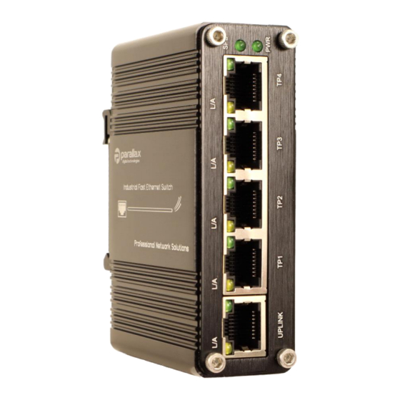
5. Product Overview The PDT-NSU-0005-I is an Unmanaged Ethernet switch, providing 5 x 10/100 RJ45 ports for connectivity, designed to directly connect to devices such as IP Cameras, Wireless APs, IP Telephones etc. This model has a wide operating voltage range (+12-48VDC) making it suitable for a wide range of... -
Page 7: Connectors And Indicators
6. Connectors and Indicators Front Panel 6.1 LED Indicators The Front Panel LEDs display the status of the switch and the associated port connections as indicated in the table below: Name Colour State Status Unit Power Off Power Green Unit Power On No Connection Link Activity Yellow... -
Page 8: Power Supply Connector
6.3 Power Supply Connector Model No Power Input PDT-NSU-0005-I +12-48VDC Note: All Power Supplies should provide over-current and short-circuit protection, and should have a capacity rating to meet the required output current for the device. -
Page 9: Installation Procedures
7. Installation Procedures 7.1 DIN Rail Installation Attach the DIN Rail Bracket (if not fitted) to Clip the upper edge of the bracket onto the the switch case using the screws supplied DIN Rail and push to latch the bottom strip 7.2 Wall Mount Installation Attach the Wall Mount Bracket (if not fitted) Mount the switch to the required surface... -
Page 10: Connection And Setup
Please inspect the unit to ensure that there is no damage to the external casing which could cause a malfunction of the device or cause a safety critical fault. Any damaged units should be returned to Parallax Digital Technologies for inspection and testing. -
Page 11: Hardware Specification
10. Hardware Specification ETHERNET Standards IEEE 802.3 Ethernet IEEE 802.3u Fast Ethernet IEEE 802.3x Full Duplex Flow Control IEEE 802.3az Energy Efficient Ethernet Forwarding and Filtering Rate 14,880pps (10Mbps) 148,800pps (100Mbps) Packet Buffer 512Kbits Packet Length 2046B MAC Address Table Exchange Property Backplane Bandwidth 20Gbps Packet Forwarding Rate 14.88Mbps... - Page 12 For all technical enquiries regarding this product, please contact our technical support team using the following email address: support@parallaxdigital.co.uk...
Need help?
Do you have a question about the PDT-NSU-0005-I and is the answer not in the manual?
Questions and answers