Table of Contents
Advertisement
Quick Links
Temperature Relays and MINIKA®
Operating Manual TR210
For more information and help about this product please scan the
choose the following link:
Operating manual, Quick guide, Datasheet, Connection diagram, CAD Data
Firmwareupdates, FAQ, Videos about installation and settings, Certificates
®
- MINIPAN
digital panel meters, temperature- and mains controlling
TR210
12430-0701-02
Mains Monitoring
Digital Panelmeters MINIPAN®
TR210
Switching Relays and Controls
Page 1 / 24
ZIEHL industrie – elektronik GmbH + Co KG
Daimlerstr.13, 74523 Schwäbisch Hall, Germany
+ 49 791 504-0,
info@ziehl.de,
Measuring Transducers
Grid- and Plant Protection
updated: 2022-12-01 / dr
from Firmware: 0-00
QR-Code
or
www.ziehl.deAA
www.ziehl.de
Advertisement
Table of Contents

Subscribe to Our Youtube Channel
Related Manuals for ZIEHL MINIPAN TR210


Summary of Contents for ZIEHL MINIPAN TR210
- Page 1 ZIEHL industrie – elektronik GmbH + Co KG Daimlerstr.13, 74523 Schwäbisch Hall, Germany + 49 791 504-0, info@ziehl.de, www.ziehl.de Temperature Relays and MINIKA® Mains Monitoring Digital Panelmeters MINIPAN® Switching Relays and Controls Measuring Transducers Grid- and Plant Protection updated: 2022-12-01 / dr...
-
Page 2: Table Of Contents
Deviations from the following requirements may therefore lead both to the loss of the statutory material defect liability rights and to the liability of the buyer for the product that has become unsafe due to the deviation from the specifications. TR210 12430-0701-02 Page 2 / 24 www.ziehl.de... -
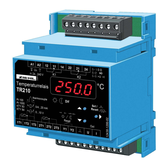
Page 3: Application And Short Description
0/4-20 mA for parameterizing (not potentially separated from the inputs) • Universal power supply AC/DC 24-240 V • Several selectable programs • Storage and indication of the measured MIN- und MAX-values • pluggable terminals 4 Connection Plan TR210 12430-0701-02 Page 3 / 24 www.ziehl.de... -
Page 4: Display And Operation Parts
2 difference 2 temperature sensors 2 MIN/MAX * factory setting Please note: Y1 / Y2 = remote – reset (external) Pr 1, 2, 5-9: Pr 3+4: Y1 / Y2 = switching day / night TR210 12430-0701-02 Page 4 / 24 www.ziehl.de... -
Page 5: Important Information
A circuit-breaker or switch must be situated within easy reach of the unit and fused. Installation excess current protection should be ≤ 10 A. TR210 12430-0701-02 Page 5 / 24 www.ziehl.de... -
Page 6: Installation
Function button UP/DOWN Press short/long Adjustment of parameter value (slow/fast) Function button SET/RESET Press short Storage of setting and choice of next parameter. Change into menu mode after the last parameter TR210 12430-0701-02 Page 6 / 24 www.ziehl.de... - Page 7 Ready for Reset is indicated with „A12L“ in the display mode. Error report: With Err it can be selected, if the relay switches in the alarm state in case of sensor-error Er1-9 (short circuit or break). (on / oFF) TR210 12430-0701-02 Page 7 / 24 www.ziehl.de...
- Page 8 - Pushing button up and down at the same time sets values to zero. - With reset (press set/reset for 2s) the display mode can be reached from every position (exception: simulation) of the parameter setting mode (the last selected value in is being stored). TR210 12430-0701-02 Page 8 / 24 www.ziehl.de...
- Page 9 = value, at which 10 V, 20 mA is put out = difference sensor 2 minus sensor 1 on, oFF = on/off = simulation CodE = code (pin) = factory setting of Pin: 504 TR210 12430-0701-02 Page 9 / 24 www.ziehl.de...
-
Page 10: Operation
= error in unit - 280 = general error ...2000 EEEE = sensor values too high -EEE = sensor values too low CodE Pi n Pi n o.k. 9999 9999 3x Er r 3x on/EL/O FF TR210 12430-0701-02 Page 10 / 24 www.ziehl.de... -
Page 11: Program 2
= error in unit = general error EEEE = sensor values too high - 280 -EEE = sensor values too low ...2000 CodE Pi n Pi n o.k. 9999 9999 3x Er r 3x on/EL/O FF TR210 12430-0701-02 Page 11 / 24 www.ziehl.de... -
Page 12: Program 3
= error in unit = general error EEEE = sensor values too high - 280 -EEE = sensor values too low ...2000 CodE Pi n Pi n o.k. 9999 9999 3x Er r 3x on/EL/O FF TR210 12430-0701-02 Page 12 / 24 www.ziehl.de... -
Page 13: Program 4
= error in unit = general error EEEE = sensor values too high - 280 -EEE = sensor values too low ...2000 CodE Pi n Pi n o.k. 9999 9999 3x Er r 3x on/EL/O FF TR210 12430-0701-02 Page 13 / 24 www.ziehl.de... -
Page 14: Program 6
= general error EEEE = sensor values too high - 280 -EEE = sensor values too low ...2000 di F CodE Pi n Pi n o.k. 9999 9999 3x Er r 3x on/EL/O FF TR210 12430-0701-02 Page 14 / 24 www.ziehl.de... -
Page 15: Program 7
= error in unit ...9999 = general error EEEE = sensor values too high -EEE = sensor values too low CodE Pi n Pi n o.k. 9999 9999 3x Er r 3x on/EL/O FF TR210 12430-0701-02 Page 15 / 24 www.ziehl.de... -
Page 16: Program 8
= error in unit = general error EEEE = sensor values too high - 1999 -EEE = sensor values too low ...9999 CodE Pi n Pi n o.k. 9999 9999 3x Er r 3x on/EL/O FF TR210 12430-0701-02 Page 16 / 24 www.ziehl.de... -
Page 17: Program 9
= general error EEEE = sensor values too high -EEE = sensor values too low - 1999 ...9999 di F CodE Pi n Pi n o.k. 9999 9999 3x Er r 3x on/EL/O FF TR210 12430-0701-02 Page 17 / 24 www.ziehl.de... -
Page 18: Action Chart
4 … 6 s. In case of sensor error the measuring time t potentiometer, the measuring time t raises to 7…10 s. TR210 12430-0701-02 Page 18 / 24 www.ziehl.de... -
Page 19: Factory Setting
(Test duration) 0-10 0-10 0-10 0-10 0-10 0-10 0-10 0-10 Type s12, s12, s12, (Sensor) ____ 0.000 0.000 0.000 (Zero) ,,,, 200.0 200.0 200.0 200.0 200.0 9.999 9.999 9.999 (Fullscale) on / oFF Code TR210 12430-0701-02 Page 19 / 24 www.ziehl.de... -
Page 20: Error Search And Measures
If after that there still is an error indicated, the unit must be sent to the factory for repair. • Indication of the software version: select display mode and pushbutton „Set“ for 10 s. TR210 12430-0701-02 Page 20 / 24 www.ziehl.de... -
Page 21: Technical Data
< 2000 m über N.N. Climatic conditions 5-85% rel. humidity, no condensation -5 °C …+70 °C External wiring temperature range 2…25 Hz ±1,6 mm, 25 ... 150 Hz 5 g Vibration resistance EN 60068-2-6 TR210 12430-0701-02 Page 21 / 24 www.ziehl.de... - Page 22 (from Fullscale) 0 – 10 V ca. 12 kΩ 27 V 0,1 % ca. 28 Ω 0/4-20 mA 100 mA *) 0,5 % *) Input protection: internal reversible fuse Temperature drift < 0,02 %/K TR210 12430-0701-02 Page 22 / 24 www.ziehl.de...
- Page 23 IP 20 Installation Snap mounting on mounting rail 35 mm according to EN 60 715 or with screws M 4 (additional bar in scope of delivery) Weight approx. 200 g Technische Änderungen vorbehalten TR210 12430-0701-02 Page 23 / 24 www.ziehl.de...
-
Page 24: Housing Design V4
For fixing to wall with screws, Ø 4,2 mm. 16 Disposal Disposal should be carried out properly and in an environmentally friendly manner in accordance with legal provisions. ZIEHL is registered with the EAR Foundation under WEEE no.: DE 49 698 543. TR210 12430-0701-02 Page 24 / 24...
Need help?
Do you have a question about the MINIPAN TR210 and is the answer not in the manual?
Questions and answers