Table of Contents
Advertisement
Quick Links
Advertisement
Table of Contents

Related Manuals for Rohde & Schwarz R&S MDS-21


Summary of Contents for Rohde & Schwarz R&S MDS-21
- Page 1 R&S MDS-21 ® Absorbing Clamp User Manual 1142.8407.04 – 02...
- Page 2 ® This document describes the R&S MDS-21 absorbing clamp. ● Material number 0194.0100.50 © 2016 Rohde & Schwarz GmbH & Co. KG Mühldorfstr. 15, 81671 Munich, Germany Phone: +49 89 41 29 - 0 Fax: +49 89 41 29 12 164 E-mail: info@rohde-schwarz.com Homepage: http://www.rohde-schwarz.com Subject to change –...
- Page 3 Basic Safety Instructions Always read through and comply with the following safety instructions! All plants and locations of the Rohde & Schwarz group of companies make every effort to keep the safety standards of our products up to date and to offer our customers the highest possible degree of safety. Our products and the auxiliary equipment they require are designed, built and tested in accordance with the safety standards that apply in each case.
- Page 4 Basic Safety Instructions Symbol Meaning Symbol Meaning Caution ! Hot surface Alternating current (AC) Protective conductor terminal Direct/alternating current (DC/AC) To identify any terminal which is intended for connection to an external conductor for protection against electric shock in case of a fault, or the terminal of a protective earth Earth (Ground) Class II Equipment...
- Page 5 Basic Safety Instructions Operating states and operating positions The product may be operated only under the operating conditions and in the positions specified by the manufacturer, without the product's ventilation being obstructed. If the manufacturer's specifications are not observed, this can result in electric shock, fire and/or serious personal injury or death. Applicable local or national safety regulations and rules for the prevention of accidents must be observed in all work performed.
- Page 6 Basic Safety Instructions 6. The product may be operated only from TN/TT supply networks fuse-protected with max. 16 A (higher fuse only after consulting with the Rohde & Schwarz group of companies). 7. Do not insert the plug into sockets that are dusty or dirty. Insert the plug firmly and all the way into the socket provided for this purpose.
- Page 7 Basic Safety Instructions 2. Before you move or transport the product, read and observe the section titled "Transport". 3. As with all industrially manufactured goods, the use of substances that induce an allergic reaction (allergens) such as nickel cannot be generally excluded. If you develop an allergic reaction (such as a skin rash, frequent sneezing, red eyes or respiratory difficulties) when using a Rohde &...
- Page 8 Basic Safety Instructions 2. Adjustments, replacement of parts, maintenance and repair may be performed only by electrical experts authorized by Rohde & Schwarz. Only original parts may be used for replacing parts relevant to safety (e.g. power switches, power transformers, fuses). A safety test must always be performed after parts relevant to safety have been replaced (visual inspection, protective conductor test, insulation resistance measurement, leakage current measurement, functional test).
- Page 9 Instrucciones de seguridad elementales Waste disposal/Environmental protection 1. Specially marked equipment has a battery or accumulator that must not be disposed of with unsorted municipal waste, but must be collected separately. It may only be disposed of at a suitable collection point or via a Rohde &...
- Page 10 Instrucciones de seguridad elementales Se parte del uso correcto del producto para los fines definidos si el producto es utilizado conforme a las indicaciones de la correspondiente documentación del producto y dentro del margen de rendimiento definido (ver hoja de datos, documentación, informaciones de seguridad que siguen). El uso del producto hace necesarios conocimientos técnicos y ciertos conocimientos del idioma inglés.
- Page 11 Instrucciones de seguridad elementales Símbolo Significado Símbolo Significado Aviso: Cuidado en el manejo de dispositivos Distintivo de la UE para la eliminación por sensibles a la electrostática (ESD) separado de dispositivos eléctricos y electrónicos Más información en la sección "Eliminación/protección del medio ambiente", punto 2.
- Page 12 Instrucciones de seguridad elementales 1. Si no se convino de otra manera, es para los productos Rohde & Schwarz válido lo que sigue: como posición de funcionamiento se define por principio la posición con el suelo de la caja para abajo, modo de protección IP 2X, uso solamente en estancias interiores, utilización hasta 2000 m sobre el nivel del mar, transporte hasta 4500 m sobre el nivel del mar.
- Page 13 Instrucciones de seguridad elementales 6. Solamente está permitido el funcionamiento en redes de alimentación TN/TT aseguradas con fusibles de 16 A como máximo (utilización de fusibles de mayor amperaje solo previa consulta con el grupo de empresas Rohde & Schwarz). 7.
- Page 14 Instrucciones de seguridad elementales Funcionamiento 1. El uso del producto requiere instrucciones especiales y una alta concentración durante el manejo. Debe asegurarse que las personas que manejen el producto estén a la altura de los requerimientos necesarios en cuanto a aptitudes físicas, psíquicas y emocionales, ya que de otra manera no se pueden excluir lesiones o daños de objetos.
- Page 15 Instrucciones de seguridad elementales Reparación y mantenimiento 1. El producto solamente debe ser abierto por personal especializado con autorización para ello. Antes de manipular el producto o abrirlo, es obligatorio desconectarlo de la tensión de alimentación, para evitar toda posibilidad de choque eléctrico. 2.
- Page 16 Instrucciones de seguridad elementales 2. Las asas instaladas en los productos sirven solamente de ayuda para el transporte del producto por personas. Por eso no está permitido utilizar las asas para la sujeción en o sobre medios de transporte como p. ej. grúas, carretillas elevadoras de horquilla, carros etc. Es responsabilidad suya fijar los productos de manera segura a los medios de transporte o elevación.
- Page 17 Customer Support Technical support – where and when you need it For quick, expert help with any Rohde & Schwarz equipment, contact one of our Customer Support Centers. A team of highly qualified engineers provides telephone support and will work with you to find a solution to your query on any aspect of the operation, programming or applications of Rohde &...
-
Page 18: Table Of Contents
R&S MDS-21 Contents Contents 1 Safety Instructions................5 2 Introduction ..................6 Front View ........................6 2.1.1 EUT Side ........................7 2.1.2 Clamp Reference Point (CRP) ..................7 2.1.3 Spacer ..........................7 2.1.4 Measuring Receiver Output ................... 7 2.1.5 Towing Ring ........................7 3 Block Diagram .................. - Page 19 R&S MDS-21 Contents User Manual 1142.8407.04 - 02...
-
Page 20: Safety Instructions
R&S MDS-21 Safety Instructions 1 Safety Instructions These operating instructions are part of the device and must be available to operating personnel at all times. All safety instructions and remarks must be observed. Improper or careless handling can be fatal. ●... -
Page 21: Introduction
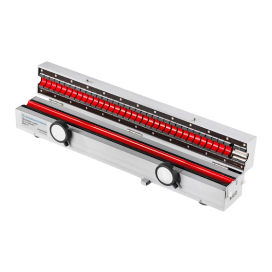
R&S MDS-21 Introduction 2 Introduction Meyer de Stadelhofen (MDS) absorbing clamps in conjunction with EMI measuring receivers are used to measure the disturbance power on cables in line with CISPR 13/EN 55013, CISPR 14-1/EN 55014-1 and EN 50083-2. They can also be used in conjunction with two-port measuring devices to measure the screening effectiveness of cables in line with IEC 62153-4 and EN 50083-2. -
Page 22: Eut Side
R&S MDS-21 Introduction 2.1.1 EUT Side This side faces the EUT. 2.1.2 Clamp Reference Point (CRP) The clamp reference point defines the position of the current transformer and is used as a reference for determining the location (distance) of the local maximum emission. 2.1.3 Spacer The spacer is used to center test cables with a small diameter, e.g. -
Page 23: Block Diagram
R&S MDS-21 Block Diagram 3 Block Diagram Fig. 2 Block diagram of the absorbing clamp User Manual 1142.8407.04 - 02... -
Page 24: Preparing For Use
R&S MDS-21 Preparing for Use 4 Preparing for Use 4.1 Unpacking the Device Remove the device from its packaging and carefully check it for any damage. Should there be any damage, inform the carrier immediately and keep the packaging to support any subsequent claims. -
Page 25: Connecting The Eut
R&S MDS-21 Preparing for Use 4.5 Connecting the EUT Place the EUT’s cable in the open absorbing clamp and use the two eccentric catches to close the clamp (see Fig. 3 below). In this position, the absorbing clamp can be opened. -
Page 26: Operation Of The Absorbing Clamp
R&S MDS-21 Operation of the Absorbing Clamp 5 Operation of the Absorbing Clamp 5.1 Function The absorbing clamp consists of a number of ferrite ring cores arranged in a row that surround the EUT’s cable. Some of these ring cores are part of the current transformer. The output voltage of the current transformer is proportional to the high-frequent current in the test cable and is fed to the measuring receiver via an internal ferrite- loaded RF cable. - Page 27 R&S MDS-21 Operation of the Absorbing Clamp A ferrite absorber in the MDS absorbing clamp surrounds the power cable and acts as resistance for the high-frequency RFI power. The incoming current is measured at the absorber input using a current transformer and an EMI measuring receiver. Since there is no matching between the disturbance source, the cable and the absorber in this setup, the MDS absorbing clamp is slid along the cable to find the maximum current.
-
Page 28: Maintenance And Upkeep
R&S MDS-21 Maintenance and Upkeep 6 Maintenance and Upkeep The device does not need any periodic maintenance. Maintenance is essentially restricted to cleaning the exterior of the device. Remove dirt from the housing with a damp cloth. Do not use aggressive cleaning agents. The measuring receiver output (N female) and the measurement cable plus the 6 dB attenuator and N angle adapter are subject to wear and tear due to mechanical and electrical influences. -
Page 29: Calibration And Recommended Recalibration Interval
R&S MDS-21 Calibration and Recommended Recalibration Interval 7 Calibration and Recommended Recalibration Interval The R&S MDS-21 absorbing clamp is calibrated by the manufacturer after production and sent to the Rohde & Schwarz warehouse together with a calibration certificate. Since the absorbing clamp is neither electrically nor mechanically stressed in the period between calibration and delivery to the warehouse and since aging of absorbing clamps in the warehouse is negligible due to the lack of active components, the interval up to the first recalibration starts on the date of delivery. -
Page 30: Index
R&S MDS-21 Index 8 Index Attenuator ................9 Unpacking ..............9 Block diagram ..............8 Disturbance power measurement example ...... 11 Calibration ............... 14 Equipment under test (EUT) ..........10 Calibration interval ............14 Front view ................6 Clamp factor ..............12 Function ................
Need help?
Do you have a question about the R&S MDS-21 and is the answer not in the manual?
Questions and answers