
Related Manuals for Sinexcel ROLECEV ULTRACHARGE 160


Summary of Contents for Sinexcel ROLECEV ULTRACHARGE 160
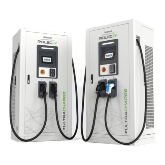
- Page 1 MAINTENANCE MANUAL ULTRACHARGE 160 Stocked in Intelligent ultra-rapid EV charging station the UK by...
-
Page 2: Product Support
Product Support Amendments Amendment Details Date Number Ver 1, Rev 0 New Document. Jan 2023 Product: UltraCharge 160 DC Charger EVDC2010 – 60kW EVDC2030 – 120kW Models: EVDC2020 – 80kW EVDC2040 – 160kW Document Type: Maintenance Manual Document Code: EVUCMM-V01R0 Language: UK English (Original) Date Published:... -
Page 3: Table Of Contents
Product Support Contents Product Support Safety Safety Advice Within this Manual Disclaimer Equipment Warnings Maintenance Maintenance of Inactive Charging Stations Charger Checks and Maintenance Cycle Replacement of Common Devices Electric Meter Main circuit breaker Cooling fan AC contactor Current transformer DC contactor Replacement of Dust Screen (Guidance) Common Troubleshooting... -
Page 4: Safety
Safety Safety This manual is specifically applicable to the UltraCharge 160 DC Charger and is provided as a guide to its maintenance. IMPORTANT: Engineers must read and understand the content of this manual before installation and/or use of the product. Engineers must be properly qualified and competent to do work on the equipment in accordance with the current legislation applicable in the geographical region of the installation. -
Page 5: Disclaimer
Disclaimer Disclaimer Rolec shall not be liable for personal injury, product damage, failure or defects in scenarios such as but not limited to: Unlicensed maintenance personnel or operators to maintain the product without authorization. The product is not maintained regularly and properly according to the requirements of the maintenance manual. -
Page 6: Equipment Warnings
Equipment Warnings Equipment Warnings Symbol Meaning Description Parts of the system are at High Power during operation. DANGER Direct or indirect contact with these components can be fatal. High voltage area may cause fire or electric shock. The construction of the area and conduits for cables must DANGER comply with national legislation. - Page 7 Equipment Warnings Each maintenance shall be recorded, components with a failure shall be identified and, the failure description shall be prepared, and they shall be sent back to the manufacturer for analysis. Do not discard carelessly. Do not change the original design of the product without authorization during maintenance.
-
Page 8: Maintenance
Maintenance Maintenance Maintenance of Inactive Charging Stations When the charger is not in use, the charger should be in a power-off state. To maintain the service life of the charger, unnecessary load should be reduced, Charger Checks and Maintenance Cycle Item Period Details... - Page 9 Maintenance Item Period Details Action Press the emergency stop button to check whether the Emergency stop Maintenance Every 6 months emergency stop button is working normally, and reset function and repairing the emergency stop button after normal check. Equipment Check whether the ground wire of the equipment Maintenance Every 6 months grounding...
-
Page 10: Replacement Of Common Devices
Maintenance Replacement of Common Devices Danger: Personal Injury Do not perform maintenance when the charger is on! Electric Meter Items required: Screwdriver. New electric meter. Replacement steps: 1. Remove the screw on the protective cover at the lower end of the electric meter, 2. -
Page 11: Main Circuit Breaker
Maintenance Main circuit breaker Items required: Hex wrench. Screwdriver. Socket wrench. Replacement steps: 1. Remove the screws in the fixed bus bar of the circuit breaker by using a hex wrench. 2. Remove the input and output bus bar with a socket wrench. -
Page 12: Cooling Fan
Maintenance Cooling fan Items required: Screwdriver. Replacement steps: 1. Remove the connecting terminals of the cooling fan; 2. Use a screwdriver to remove the four fixing screws of the fan. And then the fan can be removed. 3. Replace with a new cooling fan in an opposite sequence of disassembly. -
Page 13: Ac Contactor
Maintenance AC contactor Items required: Screwdriver. Replacement step: 1. Use a screwdriver to unscrew the six screws fixing the bus bar in the AC contactor. Note that these screws cannot be taken out and can only be unscrewed. 2. Use a screwdriver to remove the fixing screw between the bus bar and the insulation column. -
Page 14: Current Transformer
Maintenance Current transformer Items required: Screwdriver. Replacement step: 1. Use a screwdriver to remove the protective cover on the transformer then remove the connecting cable. 2. Use the screwdriver to remove the four screws of the fixed plate at the bottom of the current transformer. Then the current transformer can be removed 3. -
Page 15: Dc Contactor
Maintenance DC contactor Items required: Screwdriver. Socket wrench. Replacement steps: 1. Use a socket wrench to remove the bus bar on the DC contactor. 2. Remove the white signal line terminal on the side of the DC contactor. 3. Use the screwdriver to remove the fixing screw in the upper right corner and lower left corner of the DC contactor. -
Page 16: Replacement Of Dust Screen (Guidance)
Maintenance Replacement of Dust Screen (Guidance) Items required: Screwdriver. New dust screen. Replacement 1. Turn off the power supply, then open the left and right doors of steps: the cabinet. 2. Remove the left and right cover plates and their installation screws (M4×16) with an electric screwdriver. - Page 17 Maintenance 3. Use the pull ring of dust screen to draw out the old dust screen which will be scrapped; 4. Insert the new dust screen with the same technical parameters into the left and right-side door respectively; Note: One end of the pull ring shall be kept outside for the next change.
- Page 18 Maintenance 5. Install the side cover plate and secure the (M4×16) screw to a torque of 16kgf. Cm (1.6 Nm). NOTE: The top of the cover plate should be hung first for installation of the left cover plate, as shown in the figure, after which the screws are tightened.
-
Page 19: Common Troubleshooting
Maintenance Common Troubleshooting Failure Cause Correction Abnormal The CAN bus wiring Use a multi-meter to check whether the communication between the MCU and CAN communication line between MCU of control panel. the charging station is and the charging controller is connected loose. - Page 20 Maintenance Failure Cause Correction Black screen. Whether the power The auxiliary power supply is damaged, supply of MCU is lower or the connection is wrong. Check the than 12V. wiring. If the wiring is correct, replace the auxiliary power supply with a new one.. The power supply wire between the MCU and Tighten the power supply wire between...
-
Page 21: Emergency Unlock
Maintenance Emergency Unlock How to detach the vehicle connector when it cannot be removed in the normal manner. Follow the step below in the event of a malfunction of the electric lock in the cable connector. Warning: Electrical Hazard Make sure power to the charger is OFF before starting work. Caution: Vehicle Damage Be careful not to damage the vehicle as you work. -
Page 22: Detailed View
Maintenance 3. Push to lean the tool towards the top of the grip to depress the lock pin inside the handle. 4. Remove the tool. 5. Push the normal release button on the handle and pull the connector from the vehicle. Detailed View Release Unlocking... - Page 24 THIS DOCUMENT CONTAINS INFORMATION THAT IS SUBJECT TO CHANGE WITHOUT NOTICE. The latest version of this publication can be downloaded at https://www.rolecserv.com/downloads-ev-charging Illustrations of the product and user interface are for marketing purposes only. Brand names, logos and trademarks used herein remain the property of their respective owners. This listing of any firm or their logos is not intended to imply any endorsement or direct affiliation with Rolec Services Ltd.
Need help?
Do you have a question about the ROLECEV ULTRACHARGE 160 and is the answer not in the manual?
Questions and answers