Table of Contents
Advertisement
Advertisement
Table of Contents

Related Manuals for Case CX75SR TIER 3


Summary of Contents for Case CX75SR TIER 3
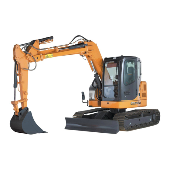
- Page 1 SERVICE MANUAL CRAWLER EXCAVATOR CX75SR CX80 TIER 3 87676026A NA Issued 01Aug 08...
- Page 2 CRAWLER EXCAVATOR CX75SR/CX80 TIER 3 SERVICE MANUAL TABLE OF CONTENTS DIVISION/SECTION SECTION N° REFERENCE N° GENERAL INFORMATION Safety, general information and standard torque data........1001 7-27691NA General specifications and special torque setting ........... 1002 SC75SRCX80-1002-0NA ENGINE Removal and installation of the engine............2000 SM75SR2000-0EN Engine specifications....................* Disassembly and assembly of the engine ..............*...
- Page 3 DIVISION/SECTION SECTION N° REFERENCE N° UPPERSTRUCTURE HYDRAULICS Specifications, troubleshooting, checks and hydraulic pressure settings................8001 SC75SRCX80-8001-0NA Removal and installation of the hydraulic reservoir .........8002 SM75SR8002-0EN Removal and installation of the main hydraulic pump........8003 SM75SR8003-0EN Removal and installation of the main hydraulic control valve - CX75SR ..8004 SM75SR8004-0EN Removal and installation of the main hydraulic control valve - CX80 ....8004 SM80-8004-0EN...
- Page 4 Section 1001 SAFETY, GENERAL INFORMATION AND TORQUE SPECIFICATIONS Copyright © 2006 CNH America LLC. All rights reverved. Printed in U.S.A. Issued February, 2006 Lep 7-27691NA Find manuals at https://best-manuals.com...
- Page 5 1001-2 TABLE OF CONTENTS GENERAL INFORMATION ............................3 SAFETY..................................4 STANDARD TORQUE DATA FOR CAP SCREWS AND NUTS................6 WARNING : This symbol is used in this manual to indicate important safety messages. Whenever you see this symbol, carefully read the message that follows, as there is a risk of serious injury. Lep 7-27691NA Issued 02-06 Find manuals at https://best-manuals.com...
- Page 6 Parts Catalog for the correct part Bearings number of the genuine Case replacement items. Failures due to the use of other than genuine Case Check bearings for easy action. If bearings have a replacement parts are not covered by warranty.
- Page 7 Operator’s and Service Manuals may be obtained from WARNING: Read the operator’s manual to your Case dealer. familiarize yourself with the correct control functions. WARNING: If you wear clothing that is too...
- Page 8 1001-5 WARNING: When servicing or repairing the WARNING: Use insulated gloves or mittens machine, keep the shop floor and operator’s when working with hot parts. compartment and steps free of oil, water, grease, tools, etc. Use an oil absorbing material and/or shop cloths as required. Use WARNING: Lower all attachments to the safe practices at all times.
- Page 9 1001-6 STANDARD TORQUE DATA FOR CAP SCREWS AND NUTS Tightening of cap screws, nuts Tighten alternately so that tightening torque can be applied evenly. The numbers in the figure below indicate the order of tightening. JS00481A Cap screws which have had Loctite used (white residue remains after removal) should be cleaned with loght oil or suitable cleaning solvent and dried.
- Page 10 Section 1002 SPECIFICATIONS AND SPECIAL TORQUE SETTINGS Copyright @ 2008 CNH America LLC. All rights reserved. Printed in USA. Lep SC75SRCX80-1002-0NA March 2008 Find manuals at https://best-manuals.com...
-
Page 11: Table Of Contents
1002-2 TABLE OF CONTENTS WARNING: This symbol is used in this manual to indicate important safety messages. Whenever you see this symbol, carefully read the message which follows. Your safety depends on it. TYPE, SERIAL NUMBER AND YEAR OF MANUFACTURE OF THE MACHINE..................... 5 Machine .................................. - Page 12 1002-3 Lower roller .................................30 Track...................................31 DIMENSIONS AND WEAR LIMITS OF ATTACHMENT LINKAGES (MONO BOOM) ...........32 1. Boom foot/Frame ..............................32 2. Boom cylinder foot/Frame............................33 3. Boom cylinder head/Boom............................33 4. Dipper cylinder foot/Boom ............................34 5. Boom/Dipper................................34 6. Dipper cylinder head/Dipper ...........................34 7. Bucket cylinder foot/Dipper.............................35 8.
- Page 13 1002-4 Lep SC75SRCX80-1002-0NA Issued 03-08...
-
Page 14: Type, Serial Number And Year Of Manufacture Of The Machine
For all part orders, request for information or assistance, always specify the type and the serial number of the machine to your Case dealer. Fill in the following lines with the required information: Type, serial number, year of manufacture of the machine and the serial numbers of the hydraulic and mechanical components. -
Page 15: Fluids And Lubricants
CASE/AKCELA: HYDRAULIC EXCAVATOR FLUID (MS 1230. ISO VG 46. DIN 51524 PART 2 HV) Hot climates: 0°C to +50°C (32° to 122° F) CASE/AKCELA: AW HYDRAULIC FLUID 68 HV (MS 1216. ISO VG 68. DIN 51524 PART 3 CATEGORY HVLP) Cold climates: -25°C to +20°C (-13° to 68° F) CASE/AKCELA: AW HYDRAULIC FLUID 32 (MS 1216. -
Page 16: Engine Oil
1002-7 Engine Oil THE CASE/AKCELA No. 1 engine oil is recommended for your engine. This oil ensures proper lubrication of your engine for all operating conditions. If the CASE/AKCELA Multigrade "No. 1 ENGINE OIL" cannot be obtained, use the oil corresponding to one of the following categories: ACEA E7 API CI-4. -
Page 17: Engine Fuel, Maintenance Of Fuel Filters And Fuel Storage
1002-8 Engine fuel, maintenance of fuel filters and fuel storage In order to meet the emission control regulation of 3rd-stage, the engine components have been made precisely and they are to be used under high-pressure conditions. Therefore, the specified fuel must be used for the engine. As a matter of course, not only the guarantee will not be given for the use of a fuel other than the specified but also it may invite a serious breakdown. - Page 18 In this case, do not use these fuels because damage to the engine may result as the fuel has been contaminated. It is natural that the emission control regulation of 3rd-stage will not be cleared in case where a fuel that does not meet the specifications and the requirements is used.
-
Page 19: Anti-Freeze/Anti-Corrosion
Never throw oil or fluid on the ground and never place it in leaking receptacles. Contact your local ecological recycling centre or your CASE Dealer to obtain information on the correct method of dis- posing of these lubricants. -
Page 20: Specifications
1002-11 SPECIFICATIONS Main data Model name ..........CX75SR, CX80 (Mono Boom), CX75SR (Offset Boom) Hydraulic Excavator Operating weight: Mono Boom ..........................7950 kg (17526.73 lbs) Mono Boom (CX80) ........................8470 kg (18673 lbs) Offset Boom (CX75SR) ......................8290 Kg (18276.3 lbs) Engine output ............................40 kW / 1800 rpm Performance Swing speed............................... -
Page 21: Cooling System
1002-12 Cooling system Fan type.................... Ø 650 mm (25.59 in), suction type - 7 blades, intake Radiator Capacity ..............................5.1L (1.3 gal) Fin type .................................. wavy Fin pitch ..............................2 mm (0.079 in) Oil cooler Capacity ..............................4.4 L (1.2 gal) Fin type .................................. -
Page 22: Hydraulic System
1002-13 Lighting Working light Cab top: 24V, 55W (x1) Boom up: 24V, 70W (x1) Interior light 24V, 6W (x1) Horn Electric horn Other Wiper with intermittent function, window washer, air conditioner, rear view mirrors, clock Hydraulic system Hydraulic pump drive system, direct engine link (no transmission) Main pump Manufacturer ............................ - Page 23 1002-14 Offset left (CX75SR) Offset Boom with blade ..............33.3 ± 0.3 MPa (4830 ± 44 psi) at 20 L/min Main relief set pressure ................. 29.4 ± 0.3 MPa (4260 ± 0.4 psi) at 44 L/min Functions Travel priority Boom up / arm 2 pumps internal flow Boom load holding circuit Arm-in forced regenerative circuit Swing priority...
-
Page 24: Hydraulic Cylinders
1002-15 Hydraulic Cylinders Mono boom spec. Offset boom spec. with dozer blade with dozer blade Boom cylinder Cylinder bore ................. Ø110 mm (Ø4.33 in) Rod diametre ................... Ø70 mm (Ø2.75 in) Maximum retracted length ...............1408 mm (55.43 in) Stroke ....................911 mm (35.87 in) Arm (dipper) cylinder Cylinder bore ................... -
Page 25: Rotating Joint
1002-16 Rotating Joint Operating pressure High pressure passage (ABCDEF).................... 29.4 MPa (4260 psi) Drain port (T) ..........................0.5 MPa (72.52 psi) Pilot port (P)........................... 3.9 MPa (566 psi) Flow High pressure passage (ABCDEF)....................68 L/min (18 gpm) Drain port (T) ..........................15 L/min (4 gpm) Pilot port (P)............................ - Page 26 1002-17 Hand control valve Manufacturer..............................Kawasaki Operating pressure .......................... 3.92 MPa (569 psi) Secondary pressure, primary short type ............0.64 to 2.45 MPa (92.82 to 355.34 psi) Operating angle Ports 1, 3 ................................19° Ports 2, 4 ................................25° Operating torque Ports 1 ........................
- Page 27 1002-18 RST-03-01-001D Foot control valve (for Dozer Blade) Manufacturer ............................Nishina industrial Operating pressure .......................... 3.92 MPa (569 psi) Secondary pressure, primary short type............0.64 to 2.45 MPa (92.82 to 355.34 psi) Operating angle................................. 10° Operating torque ..........................See the figure below Secondary pressure Operating angle (deg.)
- Page 28 1002-19 Foot control valve (for Offset Boom) (CX75SR) Manufacturer............................Nishina industrial Operating pressure .......................... 3.92 MPa (569 psi) Secondary pressure, primary short type ............0.64 to 2.45 MPa (92.82 to 355.34 psi) Operating angle ..............................12.4° Operating torque..........................See the figure below Secondary pressure Operating angle (deg.)
- Page 29 1002-20 Foot control valve (for Boom Swing) (CX80) Manufacturer ............................Nishina industrial Operating pressure .......................... 3.92 MPa (570 psi) Secondary pressure, primary short type..........0.59 ± 0.1 to 3.14 ± 0.3MPa (85.6 to 455 psi) Operating angle.............................10.0 ± 0.3° Operating torque .......................2.80 to 5.70 Nm (2.06 to 4.20 psi) Lep SC75SRCX80-1002-0NA Issued 03-08...
-
Page 30: Swing Unit
1002-21 Swing unit Swing circle ......................Swing bearing type (with internal gear) Swing hydraulic motor ..................... Fixed displacement piston motor Reduction gear....................... Planetary gear 2-stage reduction gear Swing parking brake................Mechanical lock (operational lever linkage type) Displacement .............................44.1 cm /rev Operating pressure ........................ -
Page 31: Work Unit
1002-22 Work Unit Model..............................Backhoe attachment Components / dimensions / working dimensions CX75SR Model MONO BOOM OFFSET BOOM Boom length 3870 mm (152.36 in) Arm type Standard Long Standard 1.710 mm 2.120 mm 1.750 mm (67.32 in) (83.46 in) (68.90 in) 1710 mm 2120 mm 1740 mm... - Page 32 1002-23 CX80 Model MONO BOOM Boom length 3500 mm (137.79 in) Arm type Standard Long 1.710 mm 2.120 mm (67.32 in) (83.46 in) 1710 mm 2120 mm Arm (dipper) length (67.32 in) (83.46 in) Heaped 0.28 m Heaped 0.22 m Bucket capacity (Leveled 0.20 m (Leveled 0.16 m...
-
Page 33: Component Weight
1002-24 COMPONENT WEIGHT Major component weight (CX75SR) (MONO BOOM) (OFFSET BOOM) AQ29001-001_EU Weight (kg) information is approximate Symbol Component Name MONO BOOM SPEC. OFFSET BOOM SPEC. Operating weight 7952 (17531 lbs) 8292 (18280 lbs) Upper mechanism (including coun- 3892 (8580 lbs) 3892 (8580 lbs) terweight and turntable bearing Counterweight... -
Page 34: Major Component Weight (Cx80)
1002-25 Major component weight (CX80) AS09001-001 Weight (kg) information is approximate Symbol Component Name Operating weight 8470 (18673 lbs) Upper mechanism (including counterweight and turntable bearing 4527 (9980 lbs) Counterweight 1237 (2727 lbs) Lower mechanism (with standard grouser shoe) 2801 (7175 lbs) Main Unit Weight 7328 (16155 lbs) Attachments... -
Page 35: Other Component Weight
1002-26 Other component weight Engine ..............................194 kg (427.6 lbs) Air cleaner ..............................1.7 kg (3.7 lbs) Hydraulic pump ............................51.4 kg (113 lbs) Attachment control valve Mono Boom with blade..........................82 kg (181 lbs) Mono Boom with blade (CX80) ......................85 kg (187.39 lbs) Offset boom with blade (CX75SR) ......................88 kg (194 lbs) Swing unit..............................80.0 kg (176.3 lbs) Travel unit ..............................83 kg (183 lbs) -
Page 36: Dimensions And Wear Limit Of The Track Assembly
1002-27 DIMENSIONS AND WEAR LIMIT OF THE TRACK ASSEMBLY Sprocket Dimensions Ø d Ø b Ø c CS01B512 Mark Dimension (mm) Standard Limit Standard 480.81 Ø b Limit 474.91 Standard 533.61 Ø c Limit 527.61 Standard 522.47 Ø d Limit Standard Limit Gauge... -
Page 37: Idler Wheel
1002-28 Idler wheel Dimensions Mark Dimension (mm) Standard Ø a Limit Standard Limit Standard Limit Standard Ø d (shaft) Limit Standard Ø d (bushing) Limit 42.8 Standard Ø a Limit 41.6 Standard Limit 19.5 Ø d AQ19002-001A Gauge 94 - 98 39 - 44 38.4 AQ19002-032A... -
Page 38: Upper Roller
1002-29 Upper roller Dimensions Mark Dimension (mm) Standard Ø a Limit Standard Ø b (shaft) Limit AQ19002-002A Gauge Measure with a slide caliper. Lep SC75SRCX80-1002-0NA Issued 03-08... - Page 39 1002-30 Lower roller Dimensions Øe Ø a AQ19002-003A Mark Dimension (mm) Mark Dimension (mm) Standard Standard Ø a Ø e (ring) Limit Limit 40.8 Standard Standard Limit Limit 37.6 Standard Standard 30.2 Limit Limit 29.7 Standard Ø e (shaft) Limit Gauge 150.5 - 151.5 105.7 - 106.3...
- Page 40 1002-31 Track Øf Øf' Øe Øe' Øg Øg' AQ19002-004A Mark Dimension (mm) Mark Dimension (mm) Standard Standard 41.3 Ø e (ring) Limit Limit 40.3 Standard Standard 24.5 Ø f (ring) Limit 71.5 Limit 23.8 Standard Standard 23.8 Ø g (shaft) Limit Limit 23.2...
- Page 41 This as a preview PDF file from best-manuals.com Download full PDF manual at best-manuals.com...
Need help?
Do you have a question about the CX75SR TIER 3 and is the answer not in the manual?
Questions and answers