Table of Contents
Advertisement
Quick Links
Thank you very much for purchasing this product.
• To ensure correct and safe usage with a full understanding of this product's performance, please be sure to read through this manual com-
pletely.
• Unauthorized copying or transferal, in whole or in part, of this manual is prohibited.
• The specifications of this product and the contents of this operation manual are subject to change without notice.
• The operation manual and the product have been prepared and tested as much as possible. If you find any misprints or errors, please
inform us.
• Roland DG Corporation assumes no responsibility for any direct or indirect loss or damage that may occur through use of this product,
regardless of any failure to perform on the part of this product.
• Roland DG Corporation assumes no responsibility for any direct or indirect loss or damage that may occur with respect to any article made
using this product.
FA03494/R1-230126
http://www.rolanddg.com/
Copyright © 2023 Roland DG Corporation
Advertisement
Table of Contents

Related Manuals for Roland TrueVis AP-640


Summary of Contents for Roland TrueVis AP-640
- Page 1 • Roland DG Corporation assumes no responsibility for any direct or indirect loss or damage that may occur through use of this product, regardless of any failure to perform on the part of this product. • Roland DG Corporation assumes no responsibility for any direct or indirect loss or damage that may occur with respect to any article made using this product.
-
Page 2: Table Of Contents
Contents Basic Handling Methods................6 Basic Information ...................... 7 Part Names and Functions ......................8 Printer Unit ........................8 Take-up Unit........................13 Operation Panel......................14 About the Media Used......................19 Types of Media .......................19 Conditions for Usable Media ....................20 Take-up Unit ........................21 Take-up Unit Use Conditions ....................21 About the Paper Tube .......................21 Basic Operations....................... - Page 3 Contents Changing the Print Head Height..................118 Using Media That Wrinkles Easily/Does Not Move Smoothly ............120 Using Sticky Media......................121 Using Heat-resistant Media with Minimal Waste ..............122 Setting the Take-up Unit......................123 Adjusting the Ink-drying Method ....................125 Setting the Print Heater Temperature .................
- Page 4 Contents Disposing of Discharged Fluid ..................173 Precautions for Disposing of Discharged Fluid................174 If the Discharged Fluid Disposal Message Appears ................175 Advanced Maintenance ....................177 When Dot Drop-out or Dot Displacement Occurs ................178 Performing Normal Cleaning ..................... 178 When Normal Cleaning Is Not Effective ..................180 Medium Cleaning Method....................
- Page 5 Contents Is the humidity of the room too high? .................. 212 Is the media sagging? ..................... 212 Media Feeding Is Not Straight....................213 Is the media loaded and set up straight and securely? .............. 213 Media Feeding Is Not Smooth ....................214 Is some other object coming into contact with the media? ............
- Page 6 Contents [Media End Error]......................229 [Pinch Lever Error]....................... 230 [Media Loading Error]....................230 [Loose Media Error] ...................... 231 [Drain Bottle Error] ...................... 231 [Unable to Fill Wiper Cleaning Liquid] ................231 [Print Head Height Mismatch]..................231 [Insufficient Media Width] ....................232 [Ink Supply Error]......................
-
Page 7: Basic Handling Methods
Basic Handling Methods... -
Page 8: Basic Information
Basic Information Part Names and Functions................8 Printer Unit..................8 Take-up Unit ..................13 Operation Panel ..................14 About the Media Used .................19 Types of Media ..................19 Conditions for Usable Media ..............20 Take-up Unit.....................21 Take-up Unit Use Conditions..............21 About the Paper Tube................21 Basic Information... -
Page 9: Part Names And Functions
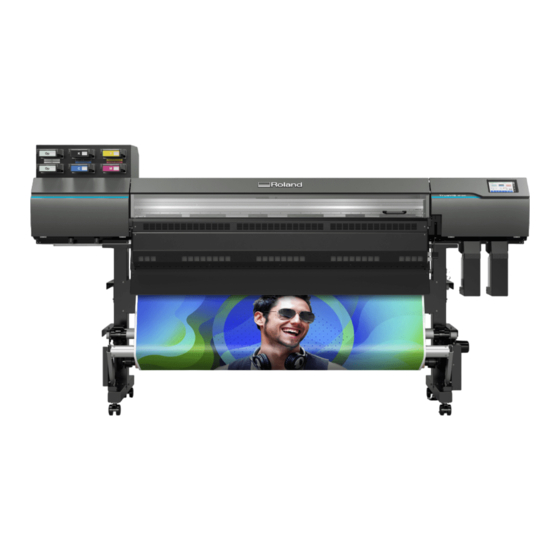
Part Names and Functions Printer Unit Front ① ② ③ ④ ⑥ ⑤ ⑦ ⑧ Name Function overview Ink slots The slots in which the pouch trays are inserted. Front cover Open this when necessary, such as when loading media. In all other situations, keep the front cover closed. - Page 10 Part Names and Functions Rear Name Function overview Loading lever (rear) Operate this when you load media. Media holders Shafts Operate this when you load media. Media stays Drain bottle (optimizer ink section) Discharged fluid is stored in this bottle. IMPORTANT Drain bottle (color ink section) Make sure that the optimizer ink and color ink section...
- Page 11 Part Names and Functions Side ① ② ③ ④ ④ ⑤ Name Function overview Ethernet connector Use this to connect an Ethernet cable. Cleaning liquid tank Holds the cleaning liquid used during maintenance. Main power switch Switches the main power on or off. Power-cord connector Use this to connect the power cable.
- Page 12 Part Names and Functions Front Cover Interior/Print Head Area ① ④ ③ ② ⑨ ⑩ ⑪ ⑤ ⑥ ⑦ ⑧ ⑫ ⑬ ⑭ Name Function overview Print light This light illuminates the front cover interior. This makes it easier to see the printing status. It flashes if a serious error oc- curs.
- Page 13 Part Names and Functions Name Function overview Print head cap (optimizer ink section) Protects the head surfaces and suctions ink during head clean- ing. Flushing pad (color ink section) To maintain print quality, ink discharged from the heads is ab- sorbed.
-
Page 14: Take-Up Unit
Part Names and Functions Take-up Unit ⑥ ① ② ③ ④ ⑤ ④ Name Function overview Motorized media holder This is used when loading the paper tube for take-up. A built-in mo- tor rotates the tube. MANUAL switch Used when taking up media manually, not with the operation panel. Control box This controls the media take-up. -
Page 15: Operation Panel
Part Names and Functions Operation Panel ① ② ⑥ ⑦ ③ ⑧ ⑨ ⑩ ④ ⑤ ⑪ ⑫ ⑬ ⑭ Name Details Displays the printer status and indicates the next opera- Status bar tion. Home Displays the home screen. Menu Displays various setting menus. - Page 16 Part Names and Functions Name Details Displays the amount of discharged fluid. When it is neces- sary to discard discharged fluid, appears. • [OP]: Amount of discharged fluid in the optimizer ink section Discharged Ink • [CMYK]: Amount of discharged fluid in the color ink section P.
- Page 17 Part Names and Functions Menu List to display the following list of operations to perform from the screen. MEMO [Media Settings] only appears when media is loaded. Level 1 Level 2 Level 3 Level 4 Details [Media Settings] [List of Media Settings] Lists the settings of the media that has been set up.
- Page 18 Part Names and Functions Level 1 Level 2 Level 3 Level 4 Details [Cleaning] [Printing Test] Before printing, use [Nozzle Drop-out Test] to check whether ink is discharged from the print heads correctly. If nozzle drop-out is present, perform cleaning appropri- ate for the severity of the drop-out.
- Page 19 Part Names and Functions Level 1 Level 2 Level 3 Level 4 Details [System Informa- [Machine Information] Displays the [Model], [Serial Number], [Ink Type], tion] [Firmware Version], and [MAC Address]. [Network] Sets the [Obtain IP Address Automatically], [IP Ad- dress], [Subnet Mask], and [Default Gateway] to con- nect the machine to a computer.
-
Page 20: About The Media Used
About the Media Used Types of Media In this manual, the paper used for output is called "media." The two main types of media used in this machine are shown below. • Roll media: Media wound onto a paper tube •... -
Page 21: Conditions For Usable Media
About the Media Used Conditions for Usable Media This machine cannot print on every kind of media. When selecting media, be sure to carry out testing in advance to make sure that satisfactory printing results are obtained. Size AP-640 Width 259 to 1,625 mm (10.2 to 64.0 in.) Maximum media thickness (including back-... -
Page 22: Take-Up Unit
Take-up Unit Take-up Unit Use Conditions Never pull the media with excessive force. If the media is pulled with excessive force, the protection function will activate and cause an error. Make sure to observe the following to prevent the media from being pulled with excessive force. •... -
Page 23: Basic Operations
Basic Operations Power Supply Operations ................23 Turning the Power On................24 Turning the Power Off ................25 Sleep Mode (Power-saving Feature) ............26 Setup of New Media ..................27 Setup of Roll Media ................27 Setup of Sheet Media ................48 Setup of Registered Media ................60 Setup of Roll Media ................60 Setup of Sheet Media ................78 Checking before Output ................87... -
Page 24: Power Supply Operations
Power Supply Operations IMPORTANT Always keep the main power switched on. Never switch off the main power. Leaving the main power enables automatic maintenance to be carried out periodical- ly. If the automatic maintenance is not carried out, it may result in the breakdown of this machine, such as the break- down of the print heads. -
Page 25: Turning The Power On
Power Supply Operations Turning the Power On WARNING When output is not being performed, remove any loaded media or switch off the sub power. The continued application of heat at a single location may cause the release of toxic gases from the media or pose a fire hazard. -
Page 26: Turning The Power Off
Power Supply Operations Turning the Power Off WARNING When output is not being performed, remove any loaded media or switch off the sub power. The continued application of heat at a single location may cause the release of toxic gases from the media or pose a fire hazard. -
Page 27: Sleep Mode (Power-Saving Feature)
Power Supply Operations Sleep Mode (Power-saving Feature) This machine is provided with a power-saving feature that switches to a low-power "sleep mode" when a fixed interval passes with no operation. The factory default for the time after which the machine switches to sleep mode is 30 minutes. -
Page 28: Setup Of New Media
Setup of New Media CAUTION Do not touch the dancer roller needlessly. The media take-up unit and feeder may move suddenly, which may result in injury. Setup of Roll Media Load the roll media on the printer. When the loading is finished, [Output possible.] is displayed as the sta- tus. - Page 29 Setup of New Media Select [Backward] or [Forward]. Tap [Save]. to go back to the original screen. Open the front cover. Move the media clamps to the outside of the grit rollers on the left and right edges respectively. Release the locking mechanisms of the media holders, and then draw them to the left and right ends re- spectively.
- Page 30 Setup of New Media • Media with an outer diameter exceeding 220 mm (8.67 in.) a. Rotate the media stays to draw them to the media holders. b. Place the media directly between the two pipes. Fit the paper tube (core) of the media onto the end cap of the left media holder. Move the right media holder to fit its end cap onto the paper tube (core) of the media.
- Page 31 Setup of New Media IMPORTANT Do not secure the media holders in place just yet. In the following procedure, you will adjust the positions of the media holders before securing them in place. Do not secure them in place just yet. The next operation to perform varies depending on the media type.
- Page 32 Setup of New Media 2. A: Determine the positions of the media (opaque media). This section describes how to use the suction fan to prevent media skewing. By default, [Skewing Correction Support at Setup] is set to [Enable]. Procedure Set the [Skewing Correction Support at Setup]. [Preferences]>[Skewing Correction Support at Setup] Select [Enable] and tap [Save].
- Page 33 Setup of New Media IMPORTANT Firmly decide the left and right side positions of the media at this point. After this procedure is completed, if the left and right side positions do not fit the proper positions when se- curing the media with pinch rollers, you will have to go back to this step to redo this procedure. If you just hold the media to readjust its position forcibly, the media will be skewed during printing, which will have an adverse effect on the printing results.
- Page 34 Setup of New Media You will hear a beep. Approximately 5 seconds later, you will hear two beeps, and then the suction fan will activate. While this fan is operating, the position of the media will be main- tained even if you remove your hands from it. Hold the media holder flange, turning it in the take-up direction to eliminate the slack in the me- dia.
- Page 35 Setup of New Media The media is held in place. Line up the edges of the media with the centers of the holes of the left and right media clamps. IMPORTANT Be sure to use the media clamps when you load media. If you attach the media clamps directly before printing after the media setup is complete, the machine may print on the media clamps.
- Page 36 Setup of New Media 2. B: Determine the positions of the media (transparent media, etc.). This section describes how to determine the positions of the media without using the suction fan. Refer to this information when using transparent media and media with high reflectance, whose edges cannot be detected.
- Page 37 Setup of New Media Otherwise the media may fall off the media holder and cause injury. IMPORTANT Firmly decide the left and right side positions of the media at this point. After this procedure is completed, if the left and right side positions do not fit the proper positions when se- curing the media with pinch rollers, you will have to go back to this step to redo this procedure.
- Page 38 Setup of New Media (Move to the front of the printer.) Gently hold down the media and raise the loading lever (front). The media is released. Hold the media at the center and pull it out, being sure to keep it straight and all areas of the media to be taut.
- Page 39 Setup of New Media IMPORTANT If you want to readjust the media position, return to the back of the printer, release the media holders, and then redo the procedure from step 1. If you just stand at the front of the printer and hold the media to read- just its position forcibly, the media will be skewed during printing or will come loose, which will affect the printing quality.
- Page 40 Setup of New Media IMPORTANT Be sure to use the media clamps when you load media. If you attach the media clamps directly before printing after the media setup is complete, the machine may print on the media clamps. Close the front cover. Basic Operations...
- Page 41 Setup of New Media 3. Register the media. Procedure [Setup]. Select [New]. Tap [Next]. Enter a new media name and tap [OK]. Tap [Next]. On the [Select Sheet Type] screen, select [Opaque]/[Transparent] and tap [Next]. The [Sheet Settings] screen appears. Configure the settings as shown below depending on the sheet type. •...
- Page 42 Setup of New Media • [Sheet Width] setting a. Tap next to [Sheet Width]. b. Enter the sheet width and tap [OK]. • [Sheet Right Edge] setting a. Tap [Change] next to [Sheet Right Edge]. b. Tap to move the carriage's base point mark to the right edge of the media, and then tap [OK].
- Page 43 Setup of New Media 4. Load the media in the take-up unit. If you will not use the take-up unit, proceed to 5. Configure settings to match the media.(P. 46). Procedure Lower the dancer roller toward the rear. Follow the procedure below to load a paper tube on the media holders of the take-up unit. Prepare a paper tube wider than the media that has been set up.
- Page 44 Setup of New Media Hold down on the operation panel to feed out the media until the tip of the media reaches the paper tube. Media is fed out 10 mm (0.39 in.) each time you hold down this button. Holding down the button lets you feed out paper continuously.
- Page 45 Setup of New Media Secure the left and right media holders. Follow the procedure below to secure the media on the paper tube. Secure the media in the [Take-up Direction] set in step 2 of 1. Install the media on the media holders.(P.
- Page 46 Setup of New Media Tap [OK]. Basic Operations...
- Page 47 Setup of New Media 5. Configure settings to match the media. To ensure the optimal output according to the media size and type, you can set the minimal amount of items. All items set here can be set individually as well. Procedure Adjust the print head height using [Print Head Height].
- Page 48 Setup of New Media Set the correction value from the printing test result. For more information, refer to Man- ual Adjustment: Reducing Horizontal Bands (Feed Correction)(P. 114). c. Tap [Save and Proceed]. d. Perform a printing test on the [Detailed Media Gap Adjustment (Manual)] screen. Set the correction value from the printing test result.
-
Page 49: Setup Of Sheet Media
Setup of New Media Setup of Sheet Media Load the sheet media on the printer. When the loading is finished, [Output possible.] is displayed as the status. This work is referred to as "Setup of Media." 1. A: Determine the positions of the media (opaque media). This section describes how to use the suction fan to prevent media skewing. - Page 50 Setup of New Media From the rear of the printer, pass the leading edge of the media between the pinch rollers (A) and the grit rollers (B). IMPORTANT If the leading edge of the media is bent, cut the bent part before loading the media, as it may be difficult for the media to enter the dryer entrance.
- Page 51 Setup of New Media Lower the loading lever (front). The media is held in place. Line up the edges of the media with the centers of the holes of the left and right media clamps. IMPORTANT Be sure to use the media clamps when you load media. If you attach the media clamps directly before printing after the media setup is complete, the machine may print on the media clamps.
- Page 52 Setup of New Media Close the front cover. Basic Operations...
- Page 53 Setup of New Media 1. B: Determine the positions of the media (transparent media, etc.). Use the following procedure to determine the positions of the media when using transparent media and media with high reflectance, whose edges cannot be detected. Procedure Set the [Skewing Correction Support at Setup].
- Page 54 Setup of New Media Pass the leading edge of the media between the pinch rollers (A) and the grit rollers (B). Lower the loading lever (rear). The media is held in place. (Move to the front of the printer.) Gently hold down the media and raise the loading lever (front). The media is released.
- Page 55 Setup of New Media Insert the leading edge of the media into the dryer. Make sure the right edge of the media is in line with the guide line (A). Lower the loading lever (front). The media is held in place. Line up the edges of the media with the centers of the holes of the left and right media clamps.
- Page 56 Setup of New Media IMPORTANT Be sure to use the media clamps when you load media. If you attach the media clamps directly before printing after the media setup is complete, the machine may print on the media clamps. Close the front cover. Basic Operations...
- Page 57 Setup of New Media 2. Register the media. Procedure [Setup]. Select [New]. Tap [Next]. Enter a new media name and tap [OK]. Tap [Next]. On the [Select Sheet Type] screen, select [Opaque]/[Transparent] and tap [Next]. The [Sheet Settings] screen appears. Configure the settings as shown below depending on the sheet type. •...
- Page 58 Setup of New Media • [Sheet Width] setting a. Tap next to [Sheet Width]. b. Enter the sheet width and tap [OK]. • [Sheet Right Edge] setting a. Tap [Change] next to [Sheet Right Edge]. b. Tap to move the carriage's base point mark to the right edge of the media, and then tap [OK].
- Page 59 Setup of New Media 3. Configure settings to match the media. To ensure the optimal output according to the media size and type, you can set the minimal amount of items. All items set here can be set individually as well. Procedure Adjust the print head height using [Print Head Height].
- Page 60 Setup of New Media Set the correction value from the printing test result. For more information, refer to Man- ual Adjustment: Reducing Horizontal Bands (Feed Correction)(P. 114). c. Tap [Save and Proceed]. d. Perform a printing test on the [Detailed Media Gap Adjustment (Manual)] screen. Set the correction value from the printing test result.
-
Page 61: Setup Of Registered Media
Setup of Registered Media CAUTION Do not touch the dancer roller needlessly. The media take-up unit and feeder may move suddenly, which may result in injury. Setup of Roll Media Load the roll media on the printer. When the loading is finished, [Output possible.] is displayed as the sta- tus. - Page 62 Setup of Registered Media to go back to the original screen. Open the front cover. Move the media clamps to the outside of the grit rollers on the left and right edges respectively. Release the locking mechanisms of the media holders, and then draw them to the left and right ends re- spectively.
- Page 63 Setup of Registered Media • Media with an outer diameter exceeding 220 mm (8.67 in.) a. Rotate the media stays to draw them to the media holders. b. Place the media directly between the two pipes. Fit the paper tube (core) of the media onto the end cap of the left media holder. Move the right media holder to fit its end cap onto the paper tube (core) of the media.
- Page 64 Setup of Registered Media IMPORTANT Do not secure the media holders in place just yet. In the following procedure, you will adjust the positions of the media holders before securing them in place. Do not secure them in place just yet. The next operation to perform varies depending on the media type and the Preferences.
- Page 65 Setup of Registered Media 2. A: Determine the positions of the media (opaque media). This section describes how to use the suction fan to prevent media skewing. By default, [Skewing Correction Support at Setup] is set to [Enable]. Procedure Set the [Skewing Correction Support at Setup]. [Preferences]>[Skewing Correction Support at Setup] Select [Enable] and tap [Save].
- Page 66 Setup of Registered Media IMPORTANT Firmly decide the left and right side positions of the media at this point. After this procedure is completed, if the left and right side positions do not fit the proper positions when se- curing the media with pinch rollers, you will have to go back to this step to redo this procedure. If you just hold the media to readjust its position forcibly, the media will be skewed during printing, which will have an adverse effect on the printing results.
- Page 67 Setup of Registered Media You will hear a beep. Approximately 5 seconds later, you will hear two beeps, and then the suction fan will activate. While this fan is operating, the position of the media will be main- tained even if you remove your hands from it. Hold the media holder flange, turning it in the take-up direction to eliminate the slack in the me- dia.
- Page 68 Setup of Registered Media The media is held in place. Line up the edges of the media with the centers of the holes of the left and right media clamps. IMPORTANT Be sure to use the media clamps when you load media. If you attach the media clamps directly before printing after the media setup is complete, the machine may print on the media clamps.
- Page 69 Setup of Registered Media 2. B: Determine the positions of the media (transparent media, etc.). This section describes how to determine the positions of the media without using the suction fan. Refer to this information when using transparent media and media with high reflectance, whose edges cannot be detected.
- Page 70 Setup of Registered Media Otherwise the media may fall off the media holder and cause injury. IMPORTANT Firmly decide the left and right side positions of the media at this point. After this procedure is completed, if the left and right side positions do not fit the proper positions when se- curing the media with pinch rollers, you will have to go back to this step to redo this procedure.
- Page 71 Setup of Registered Media (Move to the front of the printer.) Gently hold down the media and raise the loading lever (front). The media is released. Hold the media at the center and pull it out, being sure to keep it straight and all areas of the media to be taut.
- Page 72 Setup of Registered Media IMPORTANT If you want to readjust the media position, return to the back of the printer, release the media holders, and then redo the procedure from step 1. If you just stand at the front of the printer and hold the media to read- just its position forcibly, the media will be skewed during printing or will come loose, which will affect the printing quality.
- Page 73 Setup of Registered Media IMPORTANT Be sure to use the media clamps when you load media. If you attach the media clamps directly before printing after the media setup is complete, the machine may print on the media clamps. Close the front cover. Basic Operations...
- Page 74 Setup of Registered Media 3. Select the media. Procedure [Setup]. The registered media is displayed in a list. Select the media name to use. Tap [Next]. The [Sheet Settings] screen appears. Configure the settings as shown below depending on the media. •...
- Page 75 Setup of Registered Media 4. Load the media in the take-up unit. If you will not use the take-up unit, setup is complete. Procedure Lower the dancer roller toward the rear. Follow the procedure below to load a paper tube on the media holders of the take-up unit. Prepare a paper tube wider than the media that has been set up.
- Page 76 Setup of Registered Media Hold down on the operation panel to feed out the media until the tip of the media reaches the paper tube. Media is fed out 10 mm (0.39 in.) each time you hold down this button. Holding down the button lets you feed out paper continuously.
- Page 77 Setup of Registered Media Secure the left and right media holders. Follow the procedure below to secure the media on the paper tube. Secure the media in the [Take-up Direction] set in step 2 of 1. Install the media on the media holders.(P.
- Page 78 Setup of Registered Media Tap [OK]. Basic Operations...
-
Page 79: Setup Of Sheet Media
Setup of Registered Media Setup of Sheet Media Load the sheet media on the printer. When the loading is finished, [Output possible.] is displayed as the status. This work is referred to as "Setup of Media." 1. A: Determine the positions of the media (opaque media). This section describes how to use the suction fan to prevent media skewing. - Page 80 Setup of Registered Media From the rear of the printer, pass the leading edge of the media between the pinch rollers (A) and the grit rollers (B). IMPORTANT If the leading edge of the media is bent, cut the bent part before loading the media, as it may be difficult for the media to enter the dryer entrance.
- Page 81 Setup of Registered Media Lower the loading lever (front). The media is held in place. Line up the edges of the media with the centers of the holes of the left and right media clamps. IMPORTANT Be sure to use the media clamps when you load media. If you attach the media clamps directly before printing after the media setup is complete, the machine may print on the media clamps.
- Page 82 Setup of Registered Media Close the front cover. Basic Operations...
- Page 83 Setup of Registered Media 1. B: Determine the positions of the media (transparent media, etc.). Use the following procedure to determine the positions of the media when using transparent media and media with high reflectance, whose edges cannot be detected. Procedure on the operation panel.
- Page 84 Setup of Registered Media Pass the leading edge of the media between the pinch rollers (A) and the grit rollers (B). Lower the loading lever (rear). The media is held in place. (Move to the front of the printer.) Gently hold down the media and raise the loading lever (front). The media is released.
- Page 85 Setup of Registered Media Insert the leading edge of the media into the dryer. Make sure the right edge of the media is in line with the guide line (A). Lower the loading lever (front). The media is held in place. Line up the edges of the media with the centers of the holes of the left and right media clamps.
- Page 86 Setup of Registered Media IMPORTANT Be sure to use the media clamps when you load media. If you attach the media clamps directly before printing after the media setup is complete, the machine may print on the media clamps. Close the front cover. Basic Operations...
- Page 87 Setup of Registered Media 2. Select the media. Procedure [Setup]. The registered media is displayed in a list. Select the media name to use. Tap [Next]. The [Sheet Settings] screen appears. Configure the settings as shown below depending on the media. •...
-
Page 88: Checking Before Output
Checking before Output LAN (Local Area Network) Settings Check that you can perform communication through the LAN (Local Area Network). The LAN is enabled if the status LED (B) on the LAN connector located on the side of the printer is lit in green. -
Page 89: Pausing And Canceling Output
Pausing and Canceling Output You can pause and cancel output before it finishes. Pausing and Resuming Output IMPORTANT We do not recommend resuming printing because horizontal bands and uneven colors are produced at the place where printing was paused. MEMO Some menu items can be operated during output, but return to the home screen before pausing output. -
Page 90: Canceling Output
Pausing and Canceling Output Canceling Output Procedure During output, tap [Pause]. This pauses the printing operation. Tap [Cancel Output] when the following screen appears. The confirmation screen for drying appears. Tap [Yes] or [No]. IMPORTANT Select [Yes] to feed the media to the dryer. Parts exposed to the dryer may suffer damage such as deformation or deterioration, which may result in poor printing quality. -
Page 91: Separating The Media
Separating the Media After printing, use [Sheet Cutting] or [Perforated Sheet Cutting] to separate the media. Procedure Close the front cover. If necessary, use the following procedure to set the separation position. [Move]. to set the media to the separation position. The media is separated at the position in the following figure. - Page 92 Separating the Media MEMO If the media is separated even after you select [Perforated Sheet Cutting], use [Preferences]>[Perforated Sheet Cutting] to change to the [Increase Uncut Locations] setting. If the media is heavy or has a large amount that is slack, it can be retained without being separated. Tap [Execute].
-
Page 93: Removing Media From The Take-Up Unit
Removing Media from the Take-up Unit When output is complete, separate the media, take up the media manually, and then remove the media. WARNING Handling roll media is an operation that must be performed by 2 persons or more, and care must be taken to prevent falls. - Page 94 Removing Media from the Take-up Unit When using the FORWARD setting When using the BACKWARD setting Take up the media with [FORWARD]. Take up the media with [BACKWARD]. While supporting the media from below, loosen the securing lever on the left media holder. With the media supported, pull the paper tube and media from the end cap.
-
Page 95: Ink Pouch Replacement
Ink Pouch Replacement Out-of-ink Warnings When an ink pouch runs out, printing pauses and a warning beep sounds. Also, the screen [Ink has run out.] will be displayed on the operation panel to request that you replace the ink. IMPORTANT Never reuse an ink pouch when the machine shows a sign indicating no ink. -
Page 96: Ink Pouch Replacement
Ink Pouch Replacement Ink Pouch Replacement WARNING Never store ink, cleaning liquid, or discharged fluid in any of the following locations. • Any location where high temperature may occur • Near bleach or any other such oxidizing agent or explosive material •... - Page 97 Ink Pouch Replacement IMPORTANT When opening the lid, hold it as shown in the figure and do not touch (B). Doing so may cause damage. Pinch the hook (A) at the tip of the ink pouch, and then remove the ink pouch from the pouch tray. MEMO Wipe off the ink at the tip of the pouch tray.
- Page 98 Ink Pouch Replacement Remove the new ink pouch from the inner box and the plastic bag. IMPORTANT • When taking the ink pouch out of the plastic bag, do not use a utility knife or any other sharp object. Doing so may lead to accidentally cutting the ink pouch.
- Page 99 Ink Pouch Replacement Follow the procedure below to attach the tip of the ink pouch to the pouch tray. Push down until you hear a click. Insert the ink pouch into the pouch tray. Insert the back end of the ink pouch into the underside of the pouch tray roller, ensuring that this end is straight.
- Page 100 Ink Pouch Replacement Affix the ink pouch's expiration date sticker (A), included with the ink pouch, to the right side of the pouch tray ink label. 26.07.202X Set the pouch tray (A) in the ink slot. Insert the pouch tray as far as it will go. If the inserted ink is not recognized and does not show up on the operation panel, remove it and insert it again.
- Page 101 Ink Pouch Replacement Basic Operations...
-
Page 102: Cleaning Liquid Replenishment
Cleaning Liquid Replenishment Out-of-cleaning-liquid Warnings If the cleaning liquid runs out, [Fill the cleaning liquid tank with cleaning liquid.] appears on the screen. Tap [OK] to close this message. You can also check the message by tapping RELATED LINKS ・ P. -
Page 103: Cleaning Liquid Replenishment Method
Cleaning Liquid Replenishment Cleaning Liquid Replenishment Method WARNING Never store ink, cleaning liquid, or discharged fluid in any of the following locations. • Any location where high temperature may occur • Near bleach or any other such oxidizing agent or explosive material •... - Page 104 Cleaning Liquid Replenishment Close the lid of the cleaning liquid tank, and then slowly return this tank to its position in the printer. Basic Operations...
-
Page 105: Output Method
Output Method... -
Page 106: Printing Method
Printing Method Preparations before Printing Output............... 106 Step 1: Performing a Nozzle Drop-out Test..........106 Step 2: Performing Normal Cleaning ............107 Printing Output ..................109 Printing Method... -
Page 107: Preparations Before Printing Output
Preparations before Printing Output Step 1: Performing a Nozzle Drop-out Test Before you carry out actual printing, perform a printing test to ensure no dot drop-out or dot displacement occurs. If dot drop-out or dot displacement occurs, perform cleaning of the print heads (normal cleaning). MEMO When performing printing tests successively, you can select [Feed] (vertical printing) or [Scan] (horizontal printing) as the printing position for the second and later tests in comparison to the first test. -
Page 108: Step 2: Performing Normal Cleaning
Preparations before Printing Output Step 2: Performing Normal Cleaning Procedure Check for the group with dot drop-out or dot displacement by viewing the results of the printing test. The space from "A" to "B" is group A. The space from "B" to the right side is group B. MEMO If the printing-test results are difficult to interpret •... - Page 109 Preparations before Printing Output Perform a printing test again. Check to make sure the dot drop-out or dot displacement has been corrected. If the problem persists, try performing normal cleaning again. If the printer has been used for a long period, dot drop-outs may not be fixed even after performing normal cleaning two or three times.
-
Page 110: Printing Output
Printing Output CAUTION Never touch the print-head carriage while output is in progress. The print-head carriage moves at high speed. Coming into contact with the moving carriage may cause injury. Procedure Close the front cover. Make sure [Output possible.] is displayed at the top of the operation panel. Send the output data from the computer. -
Page 111: Optimizing Quality And Efficiency
Optimizing Quality and Ef- ficiency... -
Page 112: Optimizing The Output Quality
Optimizing the Output Quali- Using the Correction Functions..............112 Automatically Making Required Adjustments ..........112 Manual Adjustment: Reducing Horizontal Bands (Feed Correction) ....114 Manual Adjustment: Adjusting the Misalignment of the Ink Landing Position (Media Gap Adjustment) ..............116 Configuring Settings to Match the Properties of the Media ........118 Changing the Print Head Height ............. -
Page 113: Using The Correction Functions
Using the Correction Functions To optimize the output quality, it is effective to use some correction functions. Automatically Making Required Adjustments To optimize the output quality, corrections must match the media and printing conditions. Depending on the printing conditions, the ink landing position may be misaligned and the movement dis- tance may change subtly during media feeding. - Page 114 Using the Correction Functions ・ P. 114Manual Adjustment: Reducing Horizontal Bands (Feed Correction) ・ P. 116Manual Adjustment: Adjusting the Misalignment of the Ink Landing Position (Media Gap Adjust- ment) Optimizing the Output Quality...
-
Page 115: Manual Adjustment: Reducing Horizontal Bands (Feed Correction)
Using the Correction Functions Manual Adjustment: Reducing Horizontal Bands (Feed Correction) Perform corrections to make the band-shaped "stripes" on the printed surface less noticeable. The band-shaped "stripes" are called "horizontal bands" or "banding." Horizontal bands are caused by the subtle changes in the movement distance that occur when feeding the media depending on the media's thickness and type. - Page 116 Using the Correction Functions MEMO • If the test pattern is difficult to see, tap next to [Media Feed] to move the media to a position where it is easier to see. • If you want to hold the media to check the test pattern, tap [Execute] next to [Sheet Cutting] to separate the media.
-
Page 117: Manual Adjustment: Adjusting The Misalignment Of The Ink Landing Position (Media Gap Adjustment)
Using the Correction Functions Manual Adjustment: Adjusting the Misalignment of the Ink Landing Position (Media Gap Adjustment) This adjusts the landing position of the ink discharged from the print heads. The landing position varies according to the print head height and the thickness of the media, so we recommend that you make cor- rections to match the media you are using. - Page 118 Using the Correction Functions MEMO • If the test pattern is difficult to see, tap next to [Media Feed] to move the media to a position where it is easier to see. • If you want to hold the media to check the test pattern, tap [Execute] next to [Sheet Cutting] to separate the media.
-
Page 119: Configuring Settings To Match The Properties Of The Media
Configuring Settings to Match the Properties of the Media Changing the Print Head Height This adjusts the print head height to prevent media that is wrinkled or comes loose from the platen from contacting the print heads. You can select the print head height from [Low], [Medium], and [High]. Printing quality when the print head height is set to [Medium] or [High] may be coarser or otherwise lower than when set to [Low]. - Page 120 Configuring Settings to Match the Properties of the Media Tap [OK]. The print heads move to their original position. to go back to the original screen. MEMO • Default setting: [Low] • If degradation of printing quality occurs after raising the print head height, refer to the following informa- tion and try optimizing the quality.
-
Page 121: Using Media That Wrinkles Easily/Does Not Move Smoothly
Configuring Settings to Match the Properties of the Media Using Media That Wrinkles Easily/Does Not Move Smoothly The platen uses suction to grip the media and keep it stable. The suction force can be adjusted corre- sponding to the nature and condition of the media. Procedure Load the media. -
Page 122: Using Sticky Media
Configuring Settings to Match the Properties of the Media Using Sticky Media This setting is used to peel off the media before starting printing when using media that sticks easily to the platen. This setting is effective to prevent media jams. Note, however, that peeling off the media may cause unstable media feed. -
Page 123: Using Heat-Resistant Media With Minimal Waste
Configuring Settings to Match the Properties of the Media Using Heat-resistant Media with Minimal Waste This machine feeds media to dry the ink until it passes through the dryer after printing. Since parts ex- posed to the dryer may suffer damage such as deformation or deterioration, which may result in poor printing quality, they are normally left as a margin without printing. -
Page 124: Setting The Take-Up Unit
Setting the Take-up Unit When using a take-up unit, make sure the following settings match the take-up method and output method of the actual media. The settings will have to be changed from the defaults when: • When using weak media. •... - Page 125 Setting the Take-up Unit MEMO • Default setting: [Forward] to go back to the original screen. Optimizing the Output Quality...
-
Page 126: Adjusting The Ink-Drying Method
Adjusting the Ink-drying Method This machine is equipped with functions to improve ink adhesion and also to dry the ink. You can adjust the temperature settings to match the type of media and the printing speed. [Print Heater] This heater is used mainly to improve ink adhesion. [Dryer] This is used to dry the ink. -
Page 127: Setting The Print Heater Temperature
Adjusting the Ink-drying Method Setting the Print Heater Temperature Setting the temperature of the print heater appropriately improves ink adhesion and inhibits smudging. • With the default settings, simply switching on the power does not make the dryer warm up to the set temperature. -
Page 128: Setting The Dryer Temperature
Adjusting the Ink-drying Method Setting the Dryer Temperature Setting the temperature of the dryer appropriately dries the ink. • Basically, use the software RIP (color profile) settings for temperature. Even if you use the software RIP settings, if you need to adjust the temperature, such as when there is smudging or poor drying, change the temperature in the machine settings. -
Page 129: Setting The Temperature During Standby
Adjusting the Ink-drying Method Setting the Temperature during Standby Set the print heater temperature used when the main power and the sub power are switched on and the loading of the media is not complete. For the dryer, set the temperature used when the loading of the media is complete. -
Page 130: Optimizing Work Efficiency
Optimizing Work Efficiency Managing the Media Settings................ 130 Changing the Media Settings ..............130 Checking the Registered Media Settings ............ 131 Changing the Media Name ..............132 Duplicating Media Settings..............133 Deleting Media Settings ............... 134 Adjusting the Output-start Location............... 135 Setting the Base Point ................. -
Page 131: Managing The Media Settings
Managing the Media Settings When you set up media, register the settings that are appropriate for the media with any name. You can delete registered media or check the settings on a list here. You can also duplicate registered media and register it as new media. -
Page 132: Checking The Registered Media Settings
Managing the Media Settings Checking the Registered Media Settings Procedure Tap [Media Management]. The registered media settings are displayed in a list. Tap a media setting. Tap [List of Media Settings]. The registered media setting values are displayed in a list. Menu item Reference page [Print Head Height]... -
Page 133: Changing The Media Name
Managing the Media Settings Changing the Media Name Procedure Tap [Media Management]. The registered media settings are displayed in a list. Tap the media whose name you want to change. Tap the input field and enter the media name. You can use up to 15 alphanumeric characters. Tap [OK] to confirm your entry. -
Page 134: Duplicating Media Settings
Managing the Media Settings Duplicating Media Settings Use the following procedure to duplicate existing media settings. Procedure Tap [Media Management]. The registered media settings are displayed in a list. Tap the media setting to duplicate. Tap [Duplicate Media]. A screen for entering the name of the duplicated media appears. To create this name, [COPY] is added at the start of the name of the media being duplicated. -
Page 135: Deleting Media Settings
Managing the Media Settings Deleting Media Settings Use the following procedure to delete existing media settings. MEMO This operation cannot be performed on the media being set up. To perform this operation, first cancel media setup. Procedure Tap [Media Management]. The registered media settings are displayed in a list. -
Page 136: Adjusting The Output-Start Location
Adjusting the Output-start Location Setting the Base Point Set the base point in order to determine the area on the loaded media in which to print (the output area). The base point ( ) indicates the right edge of the output area ( ). ( : Media feed direction, : print- head carriage movement direction) You can print without setting the base point, but setting the output area enables you to use media without being wasteful and also to print on the targeted location. - Page 137 Adjusting the Output-start Location Printing-start position in feed direction (forward-back- Printing-start position in scan direction (left-right) ward) Once the position has been decided, tap [Set Base Point Here] to confirm it. The base point position is updated, and you are returned to the home screen. Optimizing Work Efficiency...
-
Page 138: Reducing Output Time
Reducing Output Time Speeding Up Output for Narrow Media This shortens output time by reducing the width of head movement to the minimum necessary. This is ef- fective when the width of the media or the output data is narrow, but in general set to [Full Width] be- cause the ink may not dry. -
Page 139: Other Useful Functions
Other Useful Functions Using the Print Light (Interior Light) You can select the status of the light that shines on the platen. Procedure Tap [Preferences]>[Print Light]. Select the status of the print light. [Auto] The light is turned on/off automatically according to the status of the printer. [On] The light is on at all times. -
Page 140: Performing Printing Tests Arranged Horizontally
Other Useful Functions Performing Printing Tests Arranged Horizontally When performing printing tests successively, you can select [Feed] (vertical printing) or [Scan] (horizontal printing) as the print position for the second and later tests in comparison to the first test. IMPORTANT This setting is disabled because media is fed to the dryer if [Execute] is selected for [Printing Test (Drying Enabled)]. -
Page 141: Optimizing Operation Management
Optimizing Operation Man- agement Managing the Operations Appropriately and Efficiently ........141 Setting the Current Date/Time and Using It for Maintenance......141 Checking the Remaining Media............... 142 Showing/Hiding Notifications ..............144 Setting the Activation Interval for Sleep Mode (Power-saving Feature) ....145 Managing the Basic Settings of the Printer ............ -
Page 142: Managing The Operations Appropriately And Efficiently
Managing the Operations Appropriately and Effi- ciently Setting the Current Date/Time and Using It for Maintenance Use the following procedure to set the current date and time. By setting this, when you perform a printing test the printing test date and time will be printed alongside the printed test pattern. Notifications prompting you to perform maintenance will also be displayed at appropriate times. -
Page 143: Checking The Remaining Media
Managing the Operations Appropriately and Efficiently Checking the Remaining Media You can display how much of the media in use is left. By setting the amount of media currently remaining at the start, the amount remaining will be constantly displayed on the screen until it reaches zero. Because the amount of media remaining is not updated automatically when you change the media, redo the setting whenever you change the media. - Page 144 Managing the Operations Appropriately and Efficiently Printing the Amount of Remaining Media Print the amount of remaining media, which is displayed on the home screen. Use this when you want to make a record of the remaining length of the media currently in use. Printing the amount of media remaining before you change the media enables you to refer to the printed record and use the value to make the setting for the remaining amount the next time you use the media.
-
Page 145: Showing/Hiding Notifications
Managing the Operations Appropriately and Efficiently Showing/Hiding Notifications Use the following procedure to show/hide the following notifications, which prompt operators to perform proper operations. Procedure Tap [Preferences]>[Notifications On/Off]. to show/hide the notifications. Displayed notification Description [Ink Expiration Date Notification] [The expiration date has passed. Re- Advises the user to replace expired ink place the expired product.] pouches. -
Page 146: Setting The Activation Interval For Sleep Mode (Power-Saving Feature)
Managing the Operations Appropriately and Efficiently Setting the Activation Interval for Sleep Mode (Power-saving Feature) This setting is used to set how long it should take until the machine goes into sleep mode (the state in which the power-saving feature is working) when no output data is received and no operations are per- formed for a continued length of time. -
Page 147: Managing The Basic Settings Of The Printer
Managing the Basic Settings of the Printer Changing the Display Language This feature sets the language displayed on the display screen of the operation panel. Procedure Tap [System Information]>[Language]. Tap [Language]. Select the display language. Tap [OK]. Tap [Save] to confirm your entry. The display language is changed, and you are returned to the home screen. -
Page 148: Changing The Units Of Measurement
Managing the Basic Settings of the Printer Changing the Units of Measurement Use the following procedure to set the units of measurement displayed on the display screen of the opera- tion panel. Procedure Tap [System Information]>[Units]. Tap [Length]. Select the unit. Tap [Save] to confirm your entry. -
Page 149: Viewing Printer Information
Managing the Basic Settings of the Printer Viewing Printer Information This is a method for viewing information of this machine, such as serial number and ink type. Procedure Tap [System Information]>[Machine Information]. You can check the following information: • [Model]: Model name •... -
Page 150: Adjusting The Brightness Of The Operation Panel
Managing the Basic Settings of the Printer Adjusting the Brightness of the Operation Panel Procedure Tap [System Information]>[Screen Brightness]. to adjust the brightness. The larger the value, the brighter the screen. Tap [Save] to confirm your entry. to go back to the original screen. MEMO •... -
Page 151: Turning Off Operation Panel Sounds
Managing the Basic Settings of the Printer Turning Off Operation Panel Sounds Use the following procedure to turn off the sound when you tap the operation panel. Procedure Tap [System Information]>[Screen Operation Sound]. Tap [Off]. The operation sound turns off. Tap [Save] to confirm your entry. -
Page 152: Returning All Settings To Factory Defaults
Managing the Basic Settings of the Printer Returning All Settings to Factory Defaults This menu returns all settings to the same as their factory defaults. The settings for [Language] and [Units] are not returned to their factory default values. Procedure Tap [Preferences]>[Reset to Factory Defaults]. -
Page 153: Maintenance
Maintenance... -
Page 154: Introduction
Introduction Important Notes on Handling and Use............. 154 Printer ................... 154 Ink Pouches..................155 Basic Maintenance Knowledge ..............156 Types and Timing of Maintenance ............156 Measures When the Printer Is Not in Use for a Prolonged Period ....... 157 Introduction... -
Page 155: Important Notes On Handling And Use
Important Notes on Handling and Use Printer • This machine is a precision device. • Never subject the machine to impacts or excessive force. • Never needlessly put your hand or fingers inside the cover, the ink-pouch ports, or other internal areas of the machine. -
Page 156: Ink Pouches
Important Notes on Handling and Use Ink Pouches • Ink pouches come in various types. • Use a type that is compatible with the printer. • Never subject the ink pouches to impacts or attempt to disassemble them. • Never drop the ink pouches or shake them forcefully. The impact may rupture the internal pouches and cause the ink to leak. -
Page 157: Basic Maintenance Knowledge
Basic Maintenance Knowledge Types and Timing of Maintenance To use this machine under its optimal conditions, it is important to perform the appropriate maintenance at the appropriate times. Regular Maintenance These are the maintenance items that are required on a daily basis. Timing Category Item... -
Page 158: Measures When The Printer Is Not In Use For A Prolonged Period
Basic Maintenance Knowledge Measures When the Printer Is Not in Use for a Prolonged Period Be sure to follow the instructions shown below when the printer is not in use for a prolonged period. IMPORTANT • Never switch off the main power. Doing so may damage the printer. •... -
Page 159: Regular Maintenance
Regular Maintenance Print Head Check before Printing ..............159 Performing a Nozzle Drop-out Test ............159 Cleaning the Machine ................160 Cleaning the Media Path ..............160 Cleaning the Knife Carriage Roller ............162 Cleaning around the Print Heads ..............163 Cleaning the Print Head Caps and Flushing Frames........ -
Page 160: Print Head Check Before Printing
Print Head Check before Printing Performing a Nozzle Drop-out Test Before you carry out actual printing, perform a printing test to ensure no dot drop-out or dot displacement occurs. If dot drop-out or dot displacement occurs, perform cleaning of the print heads (normal cleaning). MEMO When performing printing tests successively, you can select [Feed] (vertical printing) or [Scan] (horizontal printing) as the printing position for the second and later tests in comparison to the first test. -
Page 161: Cleaning The Machine
Cleaning the Machine Cleaning the Media Path Wipe away any ink or grime on the media path and other areas as part of the daily cleaning procedure. It is easy for ink or grime to affix to the media path, and, if left unattended, this will contaminate new me- dia and have a negative effect on the transport of media when it is output. - Page 162 Cleaning the Machine Grit roller These are the positions where the media is fixed in place or transported, so it is easy for grime to affix to these positions. Remove buildup of media scraps and other material using a brush. Never use a metal brush.
-
Page 163: Cleaning The Knife Carriage Roller
Cleaning the Machine Cleaning the Knife Carriage Roller Paper dust affixes to the separating knife carriage roller during media separation. Periodically wipe the area clean. WARNING Never use a solvent such as gasoline, alcohol, or thinner to perform cleaning. Doing so may cause a fire. CAUTION Before attempting cleaning, switch off the sub power and wait until the platen and dryer cool (approximately 30 minutes). -
Page 164: Cleaning Around The Print Heads
Cleaning around the Print Heads The print heads are important components that discharge ink and require periodic and appropriate main- tenance. Cleaning around the print heads is known as "manual cleaning." • If you use up the cleaning sticks and cleaning liquid used for this work, contact your authorized dealer or visit our website (http://www.rolanddg.com/). - Page 165 Cleaning around the Print Heads Ink pools in dust or dirt adhered to the print heads, and drips on- The phenomenon where dirt or dust accumulates on the print to the media. heads. When symptoms that cannot be improved with wiper tray cleaning occur When any of the symptoms given below occur and wiper tray cleaning after performing cleaning functions (normal, medium, or powerful) is not effective, clean around the print heads.
-
Page 166: Cleaning The Print Head Caps And Flushing Frames
Cleaning around the Print Heads Cleaning the Print Head Caps and Flushing Frames Required items Cleaning stick (2) Cleaning liquid bottle for mainte- nance Locations to clean with this work • Color: Locations to clean in the color ink section •... - Page 167 Cleaning around the Print Heads • If you complete the work without viewing the instructions, tap [Finish All]. Tap [OK]. The print heads move to the left end of the machine. Open the right cover. Touch the location shown in the figure to discharge any static electricity. Drip one drop of cleaning liquid onto a cleaning stick.
- Page 168 Cleaning around the Print Heads IMPORTANT • Remove all ink, even ink that has hardened. Remaining ink may cause the print heads to dry out, leading to discharge issues. • Do not pinch the part indicated by A. Doing so may damage this location, decreasing its airtightness and leading to discharge issues.
- Page 169 Cleaning around the Print Heads Dispose of the cleaning stick used in the cleaning described above. Clean the optimizer ink section with a new cleaning stick. IMPORTANT Be sure to clean with a new cleaning stick from this point. Using the same cleaning stick may lead to the opti- mizer ink and color ink mixing, resulting in ink hardening and discharge issues.
- Page 170 Cleaning around the Print Heads Use the same cleaning stick to wipe off the flushing frame in the optimizer ink section. Dispose of the cleaning stick used in the cleaning described above. Clean the following location with a new cleaning stick. Close the right cover.
-
Page 171: Cleaning The Nozzle Guards
Cleaning around the Print Heads Cleaning the Nozzle Guards Required items Cleaning stick (2) Cleaning liquid bottle for mainte- nance Locations to clean with this work • Color: Locations to clean in the color ink section • OP: Locations to clean in the optimizer ink section Color IMPORTANT •... - Page 172 Cleaning around the Print Heads Drip one drop of cleaning liquid onto a cleaning stick. Clean the location (A) in the color ink section shown in the following figure. Do not touch location B. Clean the locations shown in the following figure. Dispose of the cleaning stick used in the cleaning described above.
- Page 173 Cleaning around the Print Heads Do not touch location B. Clean the locations shown in the following figure. When you have finished cleaning, close the left cover. Tap [Finish All]. The print heads move to the right side. [Maintenance in progress.] is displayed at the top of the screen, and cleaning starts. The (approx- imate) remaining time for the procedure is displayed on the screen.
-
Page 174: Disposing Of Discharged Fluid
Disposing of Discharged Fluid Precautions for Disposing of Discharged Fluid ........... 174 If the Discharged Fluid Disposal Message Appears..........175 Disposing of Discharged Fluid... -
Page 175: Precautions For Disposing Of Discharged Fluid
Precautions for Disposing of Discharged Fluid IMPORTANT Do not store discharged fluid in a location where it is exposed to direct sunlight. When temporarily storing discharged fluid in the included drain bottle, do not store it in a location that is exposed to direct sunlight. -
Page 176: If The Discharged Fluid Disposal Message Appears
If the Discharged Fluid Disposal Message Ap- pears The [When output, cleaning, and other operations are completed, discard the discharged fluid.] mes- sage appears when a certain amount of discharged fluid has collected in the bottle. If this message ap- pears, dispose of the discharged fluid. - Page 177 If the Discharged Fluid Disposal Message Appears CAUTION Before you detach the drain bottle, be sure to wait for the screen to display [Discard the discharged fluid in the bottle.]. After discarding the discharged fluid, promptly attach the drain bottle to the machine. Failing to follow this procedure may cause discharged fluid to flow out of the tube and spill, soiling your hands or the floor.
-
Page 178: Advanced Maintenance
Advanced Maintenance When Dot Drop-out or Dot Displacement Occurs ..........178 Performing Normal Cleaning..............178 When Normal Cleaning Is Not Effective ............180 Medium Cleaning Method ..............180 Powerful Cleaning Method ..............182 Cleaning the Wiper Tray............... 184 Handling Severe Dot Drop-out and Dot Displacement .......... 185 Ink Renewal Inside Heads Method ............ -
Page 179: When Dot Drop-Out Or Dot Displacement Occurs
When Dot Drop-out or Dot Displacement Occurs If dot drop-out or dot displacement occurs, perform cleaning of the print heads (normal cleaning). Performing Normal Cleaning Procedure Check for the group with dot drop-out or dot displacement by viewing the results of the printing test. The space from "A"... - Page 180 When Dot Drop-out or Dot Displacement Occurs On completion, you will return to the original screen. Perform a printing test again. Check to make sure the dot drop-out or dot displacement has been corrected. If the problem persists, try performing normal cleaning again. If the printer has been used for a long period, dot drop-outs may not be fixed even after performing normal cleaning two or three times.
-
Page 181: When Normal Cleaning Is Not Effective
When Normal Cleaning Is Not Effective Medium Cleaning Method The print heads are important components that discharge ink. They require periodic and appropriate main- tenance. When problems such as dot drop-out are not resolved by normal cleaning, perform the more forceful "medium cleaning"... - Page 182 When Normal Cleaning Is Not Effective Tap [Execute]. Cleaning will start. On completion, you will return to the original screen. Tap [Printing Test]. Select [Nozzle Drop-out Test] and tap [Execute]. Perform a printing test again to check whether the dot drop-out and dot displacement have been corrected.
-
Page 183: Powerful Cleaning Method
When Normal Cleaning Is Not Effective Powerful Cleaning Method The print heads are important components that discharge ink. They require periodic and appropriate main- tenance. When problems such as dot drop-out are not resolved by medium cleaning, perform the more forceful "powerful cleaning"... - Page 184 When Normal Cleaning Is Not Effective Tap [Execute]. Cleaning will start. On completion, you will return to the original screen. Tap [Printing Test]. Select [Nozzle Drop-out Test] and tap [Execute]. Perform a printing test again to check whether the dot drop-out and dot displacement have been corrected.
-
Page 185: Cleaning The Wiper Tray
When Normal Cleaning Is Not Effective Cleaning the Wiper Tray If problems such as dot drop-out persist even after you have performed powerful cleaning, wash the wiper tray. WARNING Be sure to perform operations as specified by the instructions, and never touch any area not specified in the instructions. -
Page 186: Handling Severe Dot Drop-Out And Dot Displacement
Handling Severe Dot Drop-out and Dot Displace- ment Ink Renewal Inside Heads Method Perform "Ink Renewal Inside Heads" in the following situation. • When ink discharge issues such as dot drop-out are not corrected after performing cleaning using the cleaning function (normal, medium, powerful), wiper tray cleaning, and cleaning around the print heads IMPORTANT A large amount of ink will be discharged during ink renewal inside heads. - Page 187 Handling Severe Dot Drop-out and Dot Displacement IMPORTANT Depending on the media, locations on which optimizer ink is printed may be difficult to check. If it is difficult to see the optimizer ink, switch to a different media and perform the printing test again. If you have opened the front cover, close it.
- Page 188 Handling Severe Dot Drop-out and Dot Displacement Start the [Ink Renewal Inside Heads] menu. Procedure Tap [Maintenance]>[Ink Renewal Inside Heads]. Check for the group with dot drop-out or dot displacement by viewing the results of the printing test. The space from "A" to "B" is group A. The space from "B" to the right side is group B. MEMO If the printing-test results are difficult to interpret •...
- Page 189 Handling Severe Dot Drop-out and Dot Displacement Perform a printing test to check the results. Procedure [Nozzle Drop-out Test] on the home screen. Tap [Execute] next to [Printing Test]. Printing of the test pattern starts. Check whether there is dot drop-out or dot displacement in the test pattern. Missing blocks indicate dot drop-out.
-
Page 190: Emergency Measure) Cleaning The Print Head Surface
Handling Severe Dot Drop-out and Dot Displacement Emergency Measure) Cleaning the Print Head Surface When dot drop-out or dot deflection is not improved even if cleaning is performed several times, you can clean the surface of the print heads as an emergency measure. The print head surface (nozzle surface) is a very delicate mechanism, so work must be performed carefully and cautiously. -
Page 191: When The Operation Panel Is Dirty
When the Operation Panel Is Dirty Operation Panel Cleaning Method IMPORTANT Important notes on this procedure • The cloths, alcohol, and similar items used in cleaning are not included with the product. • Be sure to use a cloth when cleaning the operation panel. Liquid entering into the operation panel through its gaps may cause printer malfunctions. -
Page 192: Replacing Consumable Parts
Replacing Consumable Parts Replacing Parts for Maintenance ..............192 Replacing the Wipers ................192 Flushing Pad Replacement ..............195 Replacing the Separating Knife ..............200 Replacing Consumable Parts... -
Page 193: Replacing Parts For Maintenance
Replacing Parts for Maintenance Replacing the Wipers The wipers are components that you use when cleaning the print heads. When it is time to replace the wiper, the message [The time for wiper replacement has arrived.] ap- pears. In this situation, replace the wiper. For information about purchasing wipers, contact your authorized dealer or visit our website (http:// www.rolanddg.com/). - Page 194 Replacing Parts for Maintenance The [Wiper Replacement] screen appears. Tap [Execute] for either the target optimizer ink section or the color ink section. Tap [OK]. When [Open the right cover.] appears, open the right cover. Touch the location shown in the figure to discharge any static electricity. Pinch the parts indicated by A, and then pull the old wiper up to remove it.
- Page 195 Replacing Parts for Maintenance Attach the new wiper by inserting it from above. When the replacement of the wiper is complete, tap [Finish All]. When [Close the cover.] appears, close the right cover. When you close the right cover, you are returned to the original screen. to go back to the original screen.
-
Page 196: Flushing Pad Replacement
Replacing Parts for Maintenance Flushing Pad Replacement The flushing pad is used when the print heads spray ink in the home position. When it is time to replace the flushing pad, the message [The time for flushing pad replacement has ar- rived.] appears. - Page 197 Replacing Parts for Maintenance The [Flushing Pad Replacement] screen appears. Tap [Execute] for either the target optimizer ink section or the color ink section. Tap [OK]. When [Open the right cover.] appears, open the right cover. Remove the frame to be replaced. Place your finger on A and lift it up to remove it.
- Page 198 Replacing Parts for Maintenance IMPORTANT If you add cleaning liquid while cleaning, do not dip the cleaning stick into the tip of the cleaning liquid bot- tle. Instead, drip the cleaning liquid onto the cleaning stick. Clean off any ink on the frame. IMPORTANT Always use separate cleaning sticks when cleaning the optimizer ink and color ink sections at the same time.
- Page 199 Replacing Parts for Maintenance In the case of the flushing pad on the color ink section, fully soak in cleaning liquid using the following procedure. MEMO The flushing pad on the optimizer ink section does not need to be soaked in cleaning liquid. Remove the nozzle from the cleaning liquid bottle and pour the whole cleaning liquid into the flushing pad.
- Page 200 Replacing Parts for Maintenance Attach the frame. IMPORTANT Install the optimizer ink section and color ink section frames in their original locations. Insert the hook (A) into the back. Lower the front of the frame. The following figure is an example of the color ink section [Group B (CMYK)]. When the work is complete, tap [Finish All].
-
Page 201: Replacing The Separating Knife
Replacing the Separating Knife If the separating knife becomes dull, replace it with the included replacement knife. WARNING Be sure to perform operations as specified by the instructions, and never touch any area not specified in the instructions. Sudden movement of the machine may cause injury. CAUTION Do not touch the tip of the separating knife. - Page 202 Replacing the Separating Knife Install a new knife. Slide the knife, as far as it will go, to align it with the groove. Slowly insert the knife into the groove (A). Tighten the screw. Take care to ensure that the knife does not slip out of position at this time. Replacing Consumable Parts...
- Page 203 Replacing the Separating Knife When the separating knife replacement is finished, tap [Finish All]. When [Close the cover.] appears, close the front cover. When you close the front cover, you are returned to the original screen. to go back to the original screen. Replacing Consumable Parts...
-
Page 204: Troubleshooting Methods
Troubleshooting Methods... -
Page 205: Output Quality Problems
Output Quality Problems Printed results are coarse or contain horizontal stripes........205 Do the print heads cause dot drop-out? ............ 205 Is the print head height appropriate? ............205 Have you carried out [Feed Correction]? ..........205 Have you carried out [Media Gap Adjustment] (ink landing position correc- tion)?.................. -
Page 206: Printed Results Are Coarse Or Contain Horizontal Stripes
Printed results are coarse or contain horizontal stripes Do the print heads cause dot drop-out? Carry out a printing test and make sure no dot drop-out or dot displacement occurs. If dot drop-out or dot displacement is present, perform head cleaning. RELATED LINKS ・... -
Page 207: Is The Print Heater At A Suitable Temperature
Printed results are coarse or contain horizontal stripes Is the print heater at a suitable temperature? If the ink forms lumps or smudges, raise the temperature. Note, however, that a temperature that is too high may degrade the media or cause it to wrinkle. RELATED LINKS ・... -
Page 208: The Media Becomes Soiled When Printed
The media becomes soiled when printed Do the print heads come into contact with the media? The height of the print heads may be too low. Also, if the media is not loaded and set up correctly, it may wrinkle or come loose and contact the print heads. RELATED LINKS ・... -
Page 209: Colors Are Unstable Or Uneven
Colors are unstable or uneven Have you tried mixing the ink by shaking the pouch trays? If colors are uneven, remove the pouch trays, and then shake them gently. If uneven color issues with ink occur even after shaking the pouch tray to mix the ink, perform "Ink Renew- al Inside Heads."... -
Page 210: Are The [Media Settings] Appropriate
Colors are unstable or uneven RELATED LINKS ・ P. 137Speeding Up Output for Narrow Media Are the [Media Settings] appropriate? If the settings are not suitable for the type of media, printing may be adversely affected. Choose settings optimized for the media you are using. RELATED LINKS ・... -
Page 211: Media Feed Problems
Media Feed Problems Media Wrinkles ..................211 Is the media loaded and set up straight and securely? ........211 Was loaded media allowed to stand for some time?........211 Are the media clamps attached?............. 211 Was the media loaded while the print heater was hot? ........211 Is the temperature of the dryer too high?.......... -
Page 212: Media Wrinkles
Media Wrinkles Is the media loaded and set up straight and securely? Feeding is not smooth when the media is not straight or is tensioned unevenly on the left and right. Reload the media. RELATED LINKS ・ P. 27Setup of New Media ・... -
Page 213: Is The Humidity Of The Room Too High
Media Wrinkles Is the humidity of the room too high? Use the machine in an environment with a humidity of 40 to 60%RH (no condensation). High humidity can cause the media to sag. If sagging media is used, it may come out wrinkled. Is the media sagging? If sagging media is used, it may come out wrinkled. -
Page 214: Media Feeding Is Not Straight
Media Feeding Is Not Straight Is the media loaded and set up straight and securely? Feeding is not smooth when the media is not straight or is tensioned unevenly on the left and right. Reload the media. RELATED LINKS ・ P. -
Page 215: Media Feeding Is Not Smooth
Media Feeding Is Not Smooth Is some other object coming into contact with the media? Make sure the media does not touch anything else. This may affect output, even when the feed appears to be smooth. RELATED LINKS ・ P. 27Setup of Roll Media ・... -
Page 216: A Media Jam Occurs
A Media Jam Occurs! Is an error message displayed? If an error message is displayed because the media has jammed, immediately correct the problem. Doing so may damage the print heads. RELATED LINKS ・ P. 232[Motor Error] Is the media warped or wrinkled? Many factors can cause warping or wrinkling. -
Page 217: Is Some Other Object Coming Into Contact With The Media
A Media Jam Occurs! Is some other object coming into contact with the media? Make sure the media does not touch anything else. This may affect output, even when the feed appears to be smooth. RELATED LINKS ・ P. 27Setup of Roll Media ・... -
Page 218: Machine Problems
Machine Problems The Print Heads Do Not Move ............... 218 What to Do First ................218 If the Print Heads Still Do Not Move............218 The printer unit does not run............... 220 Is the power switched on? ..............220 Is [Output possible.] displayed? ............. 220 Are any covers open? ................ -
Page 219: The Print Heads Do Not Move
The Print Heads Do Not Move If the print-head carriage stops over the platen, take action immediately to prevent the heads from drying out. What to Do First Switch the sub power off and then back on again. If the media is jammed, also remove the media. If the print heads move to the home position (inside the right cover), it means the operation has ended successfully. - Page 220 The Print Heads Do Not Move Gently move the print-head carriage to the home position by hand. Stopping at the place where the audible click is heard locks the print-head carriage in place. Gently apply pressure from the right side to make sure the print-head carriage does not move to the left. If the print-head carriage moves to the left, move it again slowly by applying pressure from the left side and make sure it locks in place.
-
Page 221: The Printer Unit Does Not Run
The printer unit does not run Is the power switched on? Switch on the printer's main power, followed by the sub power and make sure the home screen appears. RELATED LINKS ・ P. 24Turning the Power On Is [Output possible.] displayed? Output is not performed when [Output possible.] is not displayed at the top of the operation panel. -
Page 222: Is The Lan Routing Appropriate
The printer unit does not run ・ AP-640 Setup Guide Is the LAN routing appropriate? Check whether or not the network routing is appropriate. Try connecting the computer and the machine to the same hub or connecting them directly using a cable. If this makes it possible to perform output, it means the problem may be in the network itself. - Page 223 The printer unit does not run When an ink pouch tray is removed or has not been securely loaded Securely load the ink pouch tray by pushing it all the way to the back. RELATED LINKS ・ P. 95Ink Pouch Replacement ・...
-
Page 224: The Print Heater/Dryer Does Not Become Hot
The Print Heater/Dryer Does Not Become Hot Is the media loaded? By default, simply switching on the power does not make the media heating system warm up to the preset temperature. Load the media and wait for the machine to warm up. RELATED LINKS ・... -
Page 225: Cannot Separate The Media
Cannot Separate the Media Is the separating knife installed? If the separating knife is not installed, you cannot separate the media. RELATED LINKS ・ P. 200Replacing the Separating Knife Machine Problems... -
Page 226: Messages On The Operation Panel
Messages on the Operation Panel Messages ....................226 [When output, cleaning, and other operations are completed, discard the discharged fluid.] ............... 226 [The time for manual cleaning has arrived.] ..........226 [The time for wiper replacement has arrived.]......... 226 [The time for flushing pad replacement has arrived.]......... 226 [Print head protection mode has activated.].......... -
Page 227: Messages
Tap [Flushing Pad Replacement]>[Execute] to replace the flushing pad. RELATED LINKS ・ P. 195Flushing Pad Replacement [Print head protection mode has activated.] This message appears when the ink in use may not be a product specified by Roland DG Corporation. Messages on the Operation Panel... -
Page 228: [Fill The Cleaning Liquid Tank With Cleaning Liquid.]
Messages If the ink is not a product specified by Roland DG Corporation, the speed and quality of printing will be affected by operations for preventing head malfunctions. To obtain optimal performance, we recommend that you use ink specified by Roland DG Corporation. To purchase ink, contact your authorized dealer. -
Page 229: [The Lan Cable Is Not Connected.]
Messages Install the media clamps correctly and clean their parts that are read. If this message still appears, con- tact your authorized dealer. RELATED LINKS ・ P. 27Setup of New Media ・ P. 60Setup of Registered Media [The LAN cable is not connected.] This message appears when the machine and a computer are not connected with a LAN cable. -
Page 230: Error Messages
Error Messages This section describes the error messages that may appear on the machine's display and how to take action to remedy the problem. If an error message appears, all screen operations other than switching the power off are disabled. Follow the instructions on the screen to clear the error or switch the power off before starting to operate the machine again. -
Page 231: [Pinch Lever Error]
Error Messages Insert the media to add under the loaded media. Secure the pieces of media to each other with tape. Use heat-resistant tape. [Pinch Lever Error] The loading lever was raised during media setup or after completing this setup. Lower the loading lever and redo setup. -
Page 232: [Loose Media Error]
Error Messages IMPORTANT • If the leading edge of the media is bent, cut the bent part before loading the media, as it may be difficult for the media to enter the dryer entrance. • If this does not work, start the media setup with the leading edge of the media at the entrance of the dryer. This message appears when the length of opaque media is insufficient. -
Page 233: [Insufficient Media Width]
Error Messages [Insufficient Media Width] [The print data is larger than the media width. Continue output?] This message appears when the size of the printing data is larger than the printing area of the loaded media. To continue performing output without making corrections, tap [Continue Output]. At this time, the por- tion extending beyond the printing area is not output. -
Page 234: [Print Head Dry-Out Error]
Error Messages Carefully remove the jammed media. The print heads may also be damaged. Perform head cleaning, and then perform a printing test and check the results. Has the media been pulled with excessive force? Excessive tension was applied to the media, and additional action is necessary to recover from this state. First, raise the loading lever and adjust the media to create a small amount of slack, and then switch on the sub power. -
Page 235: [Dryer Error]
Error Messages [Dryer Error] [Power Supply Error] Power is not supplied to the dryer. Check whether power is supplied to the dryer, such as if the power switch is on, the power cord is con- nected, the power breaker is not tripped, etc. [Temperature Increase Error] A problem occurred while the temperature of the dryer was increasing. -
Page 236: Appendix
Appendix... -
Page 237: Operations When Moving The Unit
Operations When Moving the Unit Preparing to Move the Machine..............237 Step 1: Removing the Media ..............237 Step 2: Discharging the Tray Cleaning Liquid ..........238 Step 3: Secure the print heads in place using the retainer......239 Step 4: Reinstalling the Machine ............ -
Page 238: Preparing To Move The Machine
Preparing to Move the Machine Before moving the machine, dispose of the discharged fluid and secure the print-head carriage in place. Attempting to move the machine without first performing these preparations may result in damage to in- ternal components due to leaking ink or damage to the print heads. IMPORTANT •... -
Page 239: Step 2: Discharging The Tray Cleaning Liquid
Preparing to Move the Machine Step 2: Discharging the Tray Cleaning Liquid Discharge the cleaning liquid that has accumulated in the wiper tray and the flushing tray. Procedure Tap [Maintenance]>[Tray Cleaning Liquid Discharge]. Tap [Execute]. The cleaning liquid in the wiper tray and flushing tray is discharged. On completion, the sub power switches off. -
Page 240: Step 3: Secure The Print Heads In Place Using The Retainer
Preparing to Move the Machine Step 3: Secure the print heads in place using the retainer. Use the retainer that was attached to the machine during its installation. Procedure Open the left cover. Remove the retainer from inside the left cover of the machine. Catch the retainer on hole A, and then use the screw to secure the retainer in the position shown in the figure. -
Page 241: Step 4: Reinstalling The Machine
Preparing to Move the Machine Step 4: Reinstalling the Machine Procedure Once the preparations are complete, move the machine with as little delay as possible. Reinstall the printer immediately, and then remove the retainer securing the print heads in place. Install the retainer at the position indicated in the figure for storage. - Page 242 Preparing to Move the Machine RELATED LINKS ・ P. 102Cleaning Liquid Replenishment Method ・ P. 163Cleaning around the Print Heads Operations When Moving the Unit...
-
Page 243: Main Specifications
Main Specifications Maximum Printing Area and Margins ............... 243 Maximum Printing Area When Using Crop Marks ..........245 Media Separation Location during Continuous Printing ......... 246 Main Specifications... -
Page 244: Maximum Printing Area And Margins
Maximum Printing Area and Margins The printing area along the horizontal plane of the loaded media (the direction in which the carriages move) is determined by the margin setting. Origin of printing coordinates Printing area Media clamp When the [Sheet Cutting] method after the previous printing operation is [Sheet Cutting]: 370 mm (14.6 in.) [Perforated Sheet Cutting]: 70 mm (2.76 in.) [Side Margin] setting value... - Page 245 Maximum Printing Area and Margins In order to allow the printing area to dry, media must be fed to the dryer up to the trailing edge of the printing area. When preparing media, leave at least 400 mm (15.75 in.) of margin from the printing area. Main Specifications...
-
Page 246: Maximum Printing Area When Using Crop Marks
Maximum Printing Area When Using Crop Marks The maximum printing area when crop marks are used is reduced from the maximum printing area when crop marks are not used by an amount equal to the crop marks. Maximum printing area Crop mark 12.5 mm (0.5 in.) 10 mm (0.4 in.) -
Page 247: Media Separation Location During Continuous Printing
Media Separation Location during Continuous Printing When a command for separating the media is sent from the computer, the separation location on the me- dia is as shown in the figure below. First page Second page Separation location When [Pullback After Printing] is •... -
Page 248: Memo
Memo This product is equipped with an "eT-Kernel Compact" eT-Kernel and a "PrCONNECT(R)/Pro" TCP/IP protocol stack, both made by eSOL Co., Ltd. eT-kernel and PrCONNECT are registered trademarks of eSOL Co., Ltd. --------------------------------------------- Redistribution and use in source and binary forms, with or without modification, are permitted provided that the following conditions are met: - Redistributions in binary form must reproduce the above copyright notice, this list of conditions, and the following disclaimer in the documentation and/or other materials provided with the distribution.
Need help?
Do you have a question about the TrueVis AP-640 and is the answer not in the manual?
Questions and answers