Table of Contents
Advertisement
Quick Links
F
P
I E L D
R O G R A M M E R
Description
The Silicon Laboratories Si50x-FPB1 kit contains the
hardware and software needed for field programming
the
Si501/2/3/4
Singe/Dual/Quad/Any-Frequency
single-wire programmable CMEMS® (CMOS + MEMS)
oscillators. The Field Programmer Board (FPB) can be
run on a USB-equipped PC.
Kit Shipment Contents
Rev. 0.1 6/13
S i 5 0 x - F P B 1 - E V B
U
G
S E R
U I D E
Features
Copyright © 2013 by Silicon Laboratories
Field programming of Silicon Laboratories'
Si501/2/3/4 CMEMS oscillators
Windows-compatible software control and
device programming
Si50x-FPB1-EVB-DS087
Advertisement
Table of Contents

Related Manuals for Silicon Laboratories Si50x-FPB1-EVB


Summary of Contents for Silicon Laboratories Si50x-FPB1-EVB
- Page 1 R O G R A M M E R S E R U I D E Description Features The Silicon Laboratories Si50x-FPB1 kit contains the Field programming of Silicon Laboratories' hardware and software needed for field programming Si501/2/3/4 CMEMS oscillators...
-
Page 2: Quick Start
Si50x-FPB1-EVB 1. Quick Start 1. Install the Si50x CMEMS® FPB Software and driver. 2. Download FPB GUI Software from www.silabs.com/Si50x-FPB1 3. Launch the Field Programmable Oscillator Software by selecting Start All Programs Silicon Laboratories Si50x Field Programmer. 4. Install blank Device Under Test (DUT) to be programmed and follow the Graphical User Interface (GUI) directions. -
Page 3: Kit Contents
Si50x-FPB1(FPB). This document also describes the operation of the Silicon Laboratories Si50x-FPB1 field programmer kit. The Si50x-FPB1 kit refers to the field programmer board hardware and software intended for field programming of the Si501, 502, 503, and 504 CMEMS oscillators. - Page 4 Si50x-FPB1-EVB 2.2. FPB-EVB GUI Quick Start Guide Type an existing OPN here and all existing Hit magnifying glass to see a list of all OPNs display below. Hit <enter> to OPNs generated by the user’s FPB. deploy OPN configuration into option drop down boxes.
- Page 5 Si50x-FPB1-EVB Right Click in the Search field to select whether you see ALL OPNs in SAP or just the OPNs created on this Field Programmer Board. Figure 3. Main Screen (2 of 2) Rev. 0.1...
- Page 6 Si50x-FPB1-EVB LED indicates target socket for programming. An error message will display if the device is in a different socket than the one targeted. User can “continue anyway” to create a sample using a different size package Returns to main screen. All settings than the desired OPN.
- Page 7 Si50x-FPB1-EVB Table 1. Drop Down Menus Drop Down Menu Selection Function Options Exit Exits GUI. Advanced Control Programmer Board Tools Allows user to enable/disable VDD and set OE High/OE Low. This is an advanced feature. Advanced Update FW Updates EVB FW with file saved to hard drive.
-
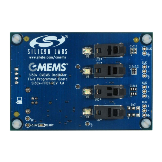
Page 8: Board Views
Si50x-FPB1-EVB 3. Board Views 3.1. Top Board View Figure 5. Top Board View Rev. 0.1... - Page 9 Si50x-FPB1-EVB 3.2. Bottom Board View Figure 6. Bottom Board View Rev. 0.1...
-
Page 10: Functional Description
Si50x-FPB1-EVB Functional Description Figure 7. Block Diagram The pages that follow provide the detailed functional description of the hardware. The FPB schematics, bill of materials, and PCB layouts are included as sections 15, 16, and 17, respectively. Figure 7 provides a block diagram for the board. - Page 11 Si50x-FPB1-EVB 4.2. MCU The Silicon Laboratories MCU, P/N C8051F380 is also mounted on the back side of the board at U 2. The MCU provides the following functions: Supports single-wire communication (C1) to the DUT on behalf of the host PC per the Field Programmable Oscillator Software ...
-
Page 12: Device Support
Si50x-FPB1-EVB 5. Device Support The FPB has four latch-able sockets installed to support four different surface mount package sizes. These are enclosed in red in Figure 8 below. To the right of each socket is the corresponding device footprint to further guide the user as to which socket supports which size package. - Page 13 Si50x-FPB1-EVB 6. USB A 4-pin USB Type B receptacle is provided at location J1. The Si50x-FB1 is compatible with USB Specification 2.0. This connector is mounted on the back of the PC board in the lower left hand corner. The location is noted on the top side with silkscreen artwork showing an icon of a PC with bidirectional arrows.
-
Page 14: Status Signals
Si50x-FPB1-EVB 7. Status Signals The five LEDs on the board are listed in Table 3. Four of these are surface mount tri-color Red, Green, Blue (RGB) LED units that report the programming status for DUTs in their respective sockets. (Note that yellow or amber is produced by mixing Red + Green light simultaneously). -
Page 15: Current Sense Resistor
Si50x-FPB1-EVB 8. Current Sense Resistor There is one current sense resistor located on the FPB designated R7 and placed between test points VDD_DUT_PIN TP15 and VDD_DUT TP16 in the center back side of the board. R7 is pointed out in the photo below. - Page 16 Si50x-FPB1-EVB 9. Outputs At this time, the Si50x-FPB1 supports only single-ended format outputs on the Si501/2/3/4 CMEMS oscillator. The three 6-pin sockets will support differential outputs on future oscillator devices. Near-end bias resistors are installed to support future devices. All outputs are ac-coupled to test points on the right hand side edge of the board (see Figure 12).
-
Page 17: Headers And Test Points
Si50x-FPB1-EVB 10. Headers and Test Points For reference purposes, all headers (JP*) and test points (TP*) are collected in Table 4. There are no headers intended for routine jumper use in the current version of the FPB. The output test points give ac-coupled access to a DUT installed in a socket. -
Page 18: Software Guide
Si50x-FPB1-EVB 11. Software Guide Users must download the Si50x CMEMS Oscillator Software, available from the Silicon Labs website at www.silabs.com/Si50x-FPB1. This software includes a User's Guide as well. The FPB SW controls the FPB and allows the user to set all configurable parameters, program devices, and generate orderable part numbers and reports. - Page 19 3. After the installation is complete, click on Start Programs Silicon Laboratories Si50x CMEMS Oscillator Software. Select one of the items in the menu including the User Guide to get more details on how to run the software.
- Page 20 Si50x-FPB1-EVB 12. Si50x CMEMS Field Programmer Oscillator Software Overview ® The FPB software supports specifying a configuration and then creating a sample or generating an Orderable Part Number or OPN. The main menus appear at the top as shown in the red rounded rectangle in the GUI excerpt below.
- Page 21 Si50x-FPB1-EVB 13. Basic Operating Instructions Basic operating instructions are illustrated in the following section based on a step by step example session. 1. Connect the Field Programmer Board by USB Once the GUI software is installed, the Field Programmer Board must be connected to any available USB port on the PC hosting the GUI software.
- Page 22 Si50x-FPB1-EVB When the USB connection is operating, the indicator turns green and a green “Ready” LED will illuminate on the Field Programmer Board. We can now move on to selecting the target device and options. Rev. 0.1...
- Page 23 Si50x-FPB1-EVB 2. Select Device Type It is recommended that option parameters are selected starting from the top with “Device Type” and proceeding sequentially downward. Pull down selections are available for most options. In this example, we select the Si503 as our target device. The Si503 allows for the selection of four programmed frequencies controlled by external pull- up and pull-down resistors at the FS/OE pin.
- Page 24 Si50x-FPB1-EVB 3. Select VDD, Jitter/Power, and Rise/Fall Time Options VDD, Jitter, Power Mode, and Rise/Fall Time (tRise/Fall) options are shown in the pull down menu. The Si501 family supports a low period jitter option that consumes slightly more power (about 1 to 2 mA) or a low-power option that results in slightly more period jitter (about 1 to ½...
- Page 25 Si50x-FPB1-EVB 4. Select Frequency Stability The Si501 frequency stability is guaranteed for 10 years of operating life. In this example, a frequency stability of ±20 ppm is selected. Rev. 0.1...
- Page 26 Si50x-FPB1-EVB 5. Select Internal Resistor Device default functionality is set to Run, Sleep, Doze, etc., according to a configurable OE selection. The internal OE pull-up is selected for this example. Refer to the device data sheet for more details on the use and external termination options of the multi-function OE pin.
- Page 27 Si50x-FPB1-EVB Note that the appearance of the GUI will change based upon the device selection. Had we selected a comparable version Si502 (the dual frequency counterpart), the window would appear as follows. In this case, the Internal Resistor selection has been replaced by the OE High | OE Wk High | OE Low | Int.
- Page 28 Si50x-FPB1-EVB 6. Specify Output Frequencies Since the Si503 is a four frequency device, each frequency must be specified. Output 1 is assigned a frequency of 32.768 kHz (for a clock timer application), output 2 to 12.288 MHz (for an audio clock application), output 3 to 24 MHz (for a USB application), and output 4 to 250 MHz.
- Page 29 Si50x-FPB1-EVB When valid frequency selections are entered, we can proceed to the next option. At this point, if any option or parameter is not properly specified, the “Create Sample & Generate OPN” button is grayed-out and Sample Creation is not yet possible. We need to make a few more selections before programming can begin.
- Page 30 Si50x-FPB1-EVB 7. Select Package For package size, the 2.0 x 2.5 mm package is selected. Once this selection is made, a blue LED will illuminate on the Field Programmer Board next to the 2.0 x 2.5 mm socket. This LED serves to guide the installation of the blank part into the proper socket.
- Page 31 Si50x-FPB1-EVB 8. Select Operating Temperature The final selection is the operating temperature range. In this example, the industrial temp range of –40 to +85 °C is selected. Rev. 0.1...
- Page 32 Si50x-FPB1-EVB 9. Create a Sample Once all options and parameters have been entered and validated, the “Create Sample & Generate OPN” button is now active. Press the “Create Sample & Generate OPN” button to start the programming process. “Create Sample”, “Create Report”,...
- Page 33 Si50x-FPB1-EVB 10. Place Blank Part in Socket At this point, place a blank part into the socket indicated by the blue LED and then press the “Confirm” button to proceed. Note: Before programming is started, make sure the socket indicated by the...
- Page 34 Si50x-FPB1-EVB The Field Programmer will first check to make sure a blank part is installed in a socket. Rev. 0.1...
- Page 35 Si50x-FPB1-EVB 11. Connect to Silicon Labs Once a blank part has been verified, the Field Programmer GUI software will check for an internet connection to Silicon Labs. If a connection has been made, but the user has not previously logged-in, log-in credentials will be required.
- Page 36 Si50x-FPB1-EVB 12. Checking and Report Generation Once connection to Silicon Labs has been established, the device will be programmed and a programming report will be created. Rev. 0.1...
- Page 37 Si50x-FPB1-EVB 13. Programming Complete The CMEMS oscillator has been successfully programmed. A sample device and an orderable part number has been created. It is now safe to remove the programmed part from the socket. Note that, once a part is programmed, it cannot be changed or re-programmed.
- Page 38 Si50x-FPB1-EVB In the future, you can select the Back button and then search for the existing part number in the Enter Part Number field. Rev. 0.1...
- Page 39 Si50x-FPB1-EVB Part numbers representing the programmer’s history will be listed as in the figure below. You can then double-click on the row to select a particular part number such as 501AAA15M0000BAF, which has been generated in the example. All fields are populated with that part number’s information on the start page and a part sample of your selection can be created as previously shown.
- Page 40 Si50x-FPB1-EVB 14. Help Help is available in various forms. “Hovering” the cursor over an entry or image on the start page, for example, will yield a brief explanation in context. For an example of this “hover help”, please see the figure below. In this case, the cursor was placed over the board image in the lower left hand corner, which triggered an information window containing the board serial number and F/W and S/W revisions.
- Page 41 Si50x-FPB1-EVB Additional help is available by selecting the Help pulldown menu and then selecting one of the options listed as illustrated below. Note that retrieval of the latest version of the User’s Guide (this document) and Device Datasheet will require internet access.
- Page 42 Si50x-FPB1-EVB 15. Tools There are a number of useful items available under the start page menu, Tools, as illustrated in the screen capture below. In this first example, Control Programmer Board has been selected. Rev. 0.1...
- Page 43 Si50x-FPB1-EVB Selecting Control Programmer Board yields the following useful page which gives the user control over the DUT’s VDD and the polarity of the Output Enable (OE) signal. The signal can be probed at the output test points to verify proper operation of the part.
- Page 44 Si50x-FPB1-EVB Another useful feature is to select Tools Check Device Orientation. If a single DUT is properly oriented in the socket, the GUI will report as follows. If not, then the FPB GUI will report one of several error messages as necessary depending on the situation: ...
- Page 45 Silicon Laboratories Si50x Field Programmer Uninstall Si50x Field Programmer. The EVB Driver (USBXpress ® ) software must be uninstalled separately via the host PC’s Control Panel. Locate and select the entry Silicon Laboratories USBXpress Device (Driver Removal) as in the figure below and click Uninstall / Change.
- Page 46 Si50x-FPB1-EVB 15. Schematics 15.1. MCU & USB Rev. 0.1...
-
Page 47: Voltage Regulators
Si50x-FPB1-EVB 15.2. Voltage Regulators Rev. 0.1... - Page 48 Si50x-FPB1-EVB 15.3. DUT Sockets Rev. 0.1...
- Page 49 Si50x-FPB1-EVB 16. Bill of Materials Table 5. Si50x-FPB Eval Board Bill of Materials Rev 1.0 Reference Value Rating Volt Type PCB_Footprint ManufacturerPN Manufacturer C1 C2 C4 C5 C7 0.1 µF 10 V ±10% C0402 C0402X7R100-104K Venkel C13 C14 C15 C16...
- Page 50 Si50x-FPB1-EVB Table 5. Si50x-FPB Eval Board Bill of Materials Rev 1.0 (Continued) Reference Value Rating Volt Type PCB_Footprint ManufacturerPN Manufacturer DS2411 SOJ6N4.45P1.27 DS2411P+ Maxim 3.2x4 mm, 6-Pin, DFN6N3.2X4-SKT- AQ10001-P Socket 2.5x3.2 mm, 6-Pin, DFN6N2.5X3.2-SKT- AM0295-580R Socket 2x2.5 mm, 4-Pin, DFN4N2X2.5-SKT-...
- Page 51 Si50x-FPB1-EVB 17. Layout Figure 17. Primary Side Assembly Figure 18. Secondary Side Assembly Rev. 0.1...
- Page 52 Si50x-FPB1-EVB Figure 19. Primary Side (Layer 1) Figure 20. Signal/Ground (Layer 2) Rev. 0.1...
- Page 53 Si50x-FPB1-EVB Figure 21. Ground (Layer 3) Figure 22. Secondary Side (Layer 4) Rev. 0.1...
- Page 54 Si50x-FPB1-EVB 18. Fabrication Drawing Rev. 0.1...
-
Page 55: Contact Information
Silicon Laboratories products are not designed, intended, or authorized for use in applications intend- ed to support or sustain life, or for any other application in which the failure of the Silicon Laboratories product could create a situation where personal injury or death may occur.
Need help?
Do you have a question about the Si50x-FPB1-EVB and is the answer not in the manual?
Questions and answers