
Subscribe to Our Youtube Channel
Related Manuals for Orlaco RLED CAN RB 4D CS


Summary of Contents for Orlaco RLED CAN RB 4D CS
- Page 1 Display 7" RLED CAN RB 4D CS User manual Manual No. UM0972011 A 01 08/2019 English Art. no.: 0208930...
-
Page 2: Table Of Contents
All data subject to change without notice. All dimensions are for commercial purpose only. The camera/display systems from Orlaco comply with the latest CE, ADR, EMC and mirror-directive regulations, where applicable. All products are manufactured in accordance with the ISO 9001 quality management system, IATF 16949 quality automotive, ISO 14001 environmental management systems, where applicable. - Page 3 Article number 0208930 ORLACO Display 7” RLED CAN RB 4D CS Used abbreviations = Auto Backlight Control = Auto Focus Zoom = Automatic Gain Control = Black Hot = Compact Color Camera = Look Up Table = Digital Detail Enhancement...
-
Page 4: Quick Reference
1. Quick Reference Keyboard Below is a brief description of the button functions. See sections 3 and 4 for a more detailed explanation. Button Button Button Button Plus + Camera Option/previ- Contrast selection ous menu select/setting Button Button Button Button Minus - Auto backlight Brightness... - Page 5 Buttons 3 and 4, setting color saturation Press the contrast (3) and brightness (4) buttons simultaneously to enable the setting mode. Set the required color saturation using the minus and plus Button buttons. This setting must be set separately for each camera. 3 + 4 Button Button 5, option/previous menu...
-
Page 6: Getting Started
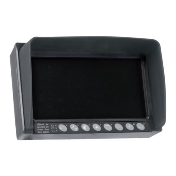
2. Getting started 2.1. Disclaimer objects in monitor are closer than they appear When switching on the monitor for the first time, a disclaimer ap- Buttons 1 2 3 4 5 6 7 8 pears in English for 5 seconds (see Figure 1). Displayed text: Do not operate display functions during safety criti- cal operations. -
Page 7: Keyboard
3. Keyboard Button 3.1. Button 1, camera selection objects in monitor are closer than they appear Press the camera selection button (1) once (see Figure 2). The Buttons 1 2 3 4 5 6 7 8 camera LED flashes to indicate that manual camera selection is enabled (see Figure 3). - Page 8 Button 3. Keyboard Button Button 3.3. Button 3, setting the contrast objects in monitor are closer than they appear Press the contrast button (3) once to enable the setting mode (see Buttons 1 2 3 4 5 6 7 8 Figure 7).
- Page 9 3. Keyboard 3.8. Quick settings When in normal image mode, the following quick settings are avail- able as shortcuts: 3.8.1. TIC camera When a TIC camera is selected and button 2 (Figure 12) is pressed, then Color LUT and DDE quick settings are enabled (indicated by illuminated button 2).
-
Page 10: Service Menu
4. Service menu Button 4. Using the service menu objects in monitor are closer than they appear To open the service menu, simultaneously press the camera selection Buttons 1 2 3 4 5 6 7 8 button (1), the minus button (6) and the plus button (7) (see Figure 13). - Page 11 4. Service menu 4.1.9. Cinema mode The camera image is displayed in widescreen when this option is enabled. 4.1.10. Camera type Select the camera type that is connected. The special features of that camera type will then become available. The camera types that can be selected are: AFZ: Enable this option if an AFI/AF zoom camera is connected.
- Page 12 4. Service menu 4.1.17. Spot meter Only works if TIC is selected as the camera type (see section 4.1.10. on page 11): OFF (spot meter off) B C (bar in Celsius) B F (bar in Fahrenheit) N C (number in Celsius) N F (number in Fahrenheit) Figure 19 BNC (bar + number in Celsius)
- Page 13 This option opens the settings menu for the keyboard lock. It is possible to lock various functions in order to prevent any unwanted Figure 25 changes. See Figure 27. The keyboard sound and beeper volume functions are not avail- able on all Orlaco displays. Figure 27 Figure 26 UM0972011 A 01...
- Page 14 CAN protocol This option selects the signal, or CAN protocol, that the display uses. By default this is Orlaco CAN protocol 1. For the Orlaco Radar system, Orlaco CAN protocol 6 must be set. Other protocols are customer-specific. The CAN speed is automatically adjusted, but it can also be set manually once the protocol has been selected.
- Page 15 This option opens the menu to restore the factory default settings. Select the number of the factory settings that you require (1 = default Orlaco settings). You can choose between 16 sets of default Figure 33 settings. Contact ORLACO for further information. Select the option 'Restore defaults' to restore the factory settings.
-
Page 16: Operator Menu
Button 5. Operator menu 5. Using the operator menu objects in monitor are closer than they appear The operator menu is not available by default due to the keyboard lock. Buttons 1 2 3 4 5 6 7 8 Button To disable the lock, refer to system settings on page 13. - Page 17 Figure 40 Figure 41 5.3. Video channel settings See Figure 41. This option sets the video channel for the Orlaco Spectrum Scanner (see Figure 42). The following options are available: CH0 = channel 0 to CH7 = channel 7 Figure 42...
-
Page 18: System Overview
6. System overview 1 camera system RLED Serial power 2 camera system With Y-split cable RLED/LEDD power 2-4 camera cable UM0972011 A 01... - Page 19 6. System overview 4 camera system With Y-split cable RLED/LEDD power 2-4 camera cable Switcher UM0972011 A 01...
-
Page 20: Overview Of Menus
7. Overview of menus Standby menu Enter Standby menu Standby Display is on but there is no picture Info Software information Operator menu The operator menu is not available by default due to the keyboard lock. Minus- and Plus buttons Operator menu English, Dutch, German, French, Czech, Italian, Polish, Portuguese, Spanish, Turkish, Swedish, Finnish, Danish, Norwegian. -
Page 21: Version Details
8. Version details A 01. First issue, August 2019 UM0972011 A 01... - Page 22 ORLACO Orlaco is a manufacturing company specialize in making camera-, and monitor systems for commercial vehicles, fork-lift trucks, cranes, off shore and maritime. Our objective is to design and produce camera systems for the professional market that improve the drivers view and increase operating efficiency.
Need help?
Do you have a question about the RLED CAN RB 4D CS and is the answer not in the manual?
Questions and answers