Table of Contents
Advertisement
Quick Links
Advertisement
Table of Contents

Related Manuals for Resonance VM200


Summary of Contents for Resonance VM200
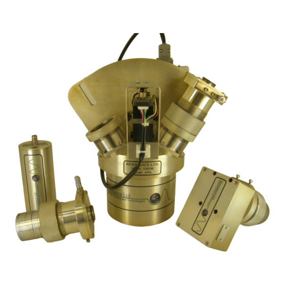
- Page 1 615 – VM200 VUV Monochromator/ Spectrometer Operating Manual www.resonance.on.ca...
-
Page 2: Table Of Contents
ERFORMING A ....................9 PERATING IN PECTROMETER MODE ..........................9 BTAINING PECTRA MOUNTING AND OPERATING WITH A LAMP .................11 CALIBRATING THE MONOCHROMATOR ..................12 FOCUSING THE VM200 ...........................13 ........................13 ONOCHROMATOR MODE ........................14 PECTROMETER MODE ADD-ON OPTIONS ............................15 APPENDIX: ..............................16 ..........................16 YSTEM OMPONENTS Monochromator ..........................16... -
Page 3: Table Of Figures
ABLE OF IGURES 1: C VM200 ......................4 IGURE UTAWAY VIEW OF 2: M ....................7 IGURE OTOR RIVE ONTROLLER 3: D ......................7 IGURE ETECTOR ONNECTIONS 4: P & Z ................ 8 IGURE HOTODIODE NDICATOR IGHTS UTTON 5: S .................. -
Page 4: General Information
YSTEM VERVIEW The Resonance Ltd. monochromator/spectrometer is designed for laboratory applications yet is rugged enough for field use. The system is hermetically sealed and can be used in the vacuum ultraviolet region (wavelengths below 190 nm) with a nitrogen or helium purge, or by connecting to a vacuum system either through the slits or through a 2.75"... -
Page 5: Packing List
ACKING Below is a list of all the components shipped with the VM200. If you find any of these items to be missing, please contact Resonance Ltd. to arrange to have it delivered. Item Quantity VM200 Monochromator Motor Drive Electonics Box... -
Page 6: Setup
ETUP The VM200 is supplied with either an exit slit, to allow use of the system as a monochromator, or a CCD for spectrometer operation or both. In monochromator mode, a detector can be mounted at the exit slit either by a 2 ¾” CF flange or a 1”-20 thread with a shoulder to hold and compress the o-ring (if vacuum... -
Page 7: System Operation
YSTEM PERATION PERATING IN ONOCHROMATOR MODE 1. Plug the motor cable into the motor drive controller box Figure 2: Motor Drive Controller Box 2. Plug in the driver box power supply 3. Plug in the USB cable 4. Plug in the LabJack USB cable 5. -
Page 8: Performing A Scan
7. Start the Program 8. Make sure the ‘Stepper’ and ‘Photodiode’ indicator lights both turn green 9. Click on the ‘Zero’ button Indicator lights Figure 4: Photodiode Indicator Lights & Zero Button 1. You are now ready to obtain spectra ERFORMING A 1. -
Page 9: Perating In Pectrometer Mode
PERATING IN PECTROMETER MODE 1. Repeat steps 1-3 from monochromator mode 2. Plug in the CCD USB cable Figure 6: CCD USB Port 3. Start the program 4. Make sure the ‘Stepper’ and ‘CCD’ indicator lights both turn green 5. Click on the ‘Zero’ button Indicator lights Figure 7: CCD Indicator Lights &... -
Page 10: Figure 8: Slit Width Adjustment Micrometer
Figure 8: Slit Width Adjustment Micrometer 2. Set the integration time and the number of averages to the desired levels. (Note: at higher signal levels [>2000 counts] the CCD begins to respond non- linearly, resulting in the appearance of loss of resolution and a rounded peak, therefore it is idea to adjust the integration time to keep the signal to a reasonable level). -
Page 11: Mounting And Operating With A Lamp
OUNTING AND PERATING WITH A Any of the several Resonance VUV lamps may be screwed directly onto the 1”-20 thread at the spectrometers entrance slit to bring the as close to the slit as possible. For other light sources, a 2 ¾” CF adapter flange with ¼”-28 threaded holes has been provided to allow easy coupling to the system. -
Page 12: Calibrating The Monochromator
ALIBRATING THE ONOCHROMATOR It is possible that occasionally the wavelength scale may need recalibration. To do this, 3 known wavelengths are required, ideally with two of them near the far ends of the wavelength scale. 1. With the light source one, scan across the spectrum 2. -
Page 13: Focusing The Vm200
VM200 OCUSING THE If for some reason you suspect that VM200 may need to be refocused, this can be done using either the detector for in monochromator mode, or the CCD in spectrometer mode. Focusing is done much quicker and simpler with the CCD, however instructions for performing this task in either mode are provided. -
Page 14: I N Spectrometer Mode
PECTROMETER MODE 1. Select a light source with a known sharp line and connect it to the monochromator 2. Set the slits to as narrow as possible while still obtaining a decent signal 3. Scan so that the line is centered in the CCD 4. -
Page 15: Add-On Options
PTIONS Adjustable Slit Assemlies Motorized Scanning Software Control Adaptor Flange for Purged Operation RF Light Source Pumping Station CCD Array EUV/VUV/UV/Vis detector... -
Page 16: Appendix
PPENDIX YSTEM OMPONENTS ONOCHROMATOR The VM200 monochromator (Vacuum Monochromator 200mm focal length) contains a concave holographic grating with AlMgF2 coating. This grating has the following specifications: Model #: VM200 Serial #: No. of lines/mm: 1200 l/mm Diameter: 40 x 45mm... -
Page 17: Photodiode Detector
1, 2, 4, 5, 8, 10, 20 Figure 13: Typical response curve of the AXUV photodiode (go to http://www.ird- inc.com/text/axuvopeprin.txt for complete date table) Resonance Ltd. uses a Hamamatsu CCD array modified to allow detection of EUV/VUV radiation. Type: Linear CCD, 2048 elements Height/Width of Active Area: 0.2 x 28 mm... -
Page 18: Adjustable Slits
Figure 14: Typical response curve of the Hamamatsu S9840 CCD DJUSTABLE LITS Resonance Ltd. uses ThorLabs Adjustable slits modified to be compatible with vacuum operations. Slit Height: 1 mm 0 – 6 mm Slit Width Range: Blade Parallelism: < 25 µm Slit Width Accuracy: ±... -
Page 19: Nist Calibration
NIST Calibration Figure 15: NIST Standard Calibration Curve UV Diode NIST Calibration NIST Standard Customer Diode Wavelength (nm) Figure 16: NIST Calibration Measurements... -
Page 20: Figure 17: Nist Traceable Quantum Efficiency Chart
NIST Traceable Calibration NIST Transfer standard diode 02-126 with <3% QE annual drift as of 2005 NIST Transfer Standard Signal Customer Diode Signal Standard QE Curve Customer Diode QE Wavelength (nm) Figure 17: NIST Traceable Quantum Efficiency Chart...
Need help?
Do you have a question about the VM200 and is the answer not in the manual?
Questions and answers