Table of Contents
Advertisement
Quick Links
Advertisement
Table of Contents

Related Manuals for Silvertel Ag9330


Summary of Contents for Silvertel Ag9330
- Page 1 Silvertel Ag9330 Evaluation Board User Manual Rev 1.0 – July 2012...
-
Page 2: Table Of Contents
Ag9330 Evaluation Board User Manual 1 Table of Contents Table of Contents Table of Figures Introduction Board Description Input Selection ..................... 3 Class Programming ..................... 4 Data Output ......................4 ... -
Page 3: Introduction
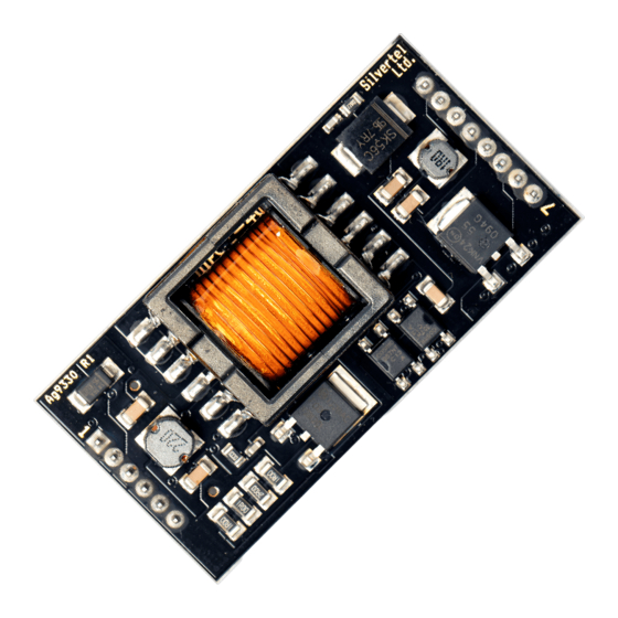
Introduction This manual is intended to be a guide to using the “EVALAG9330 evaluation board” with a Silvertel Ag9330 Powered Device (PD) module. 4 Board Description The data is supplied to the EVALAG9330 board through connector J1 and is passed through to the peripheral equipment via J2. -
Page 4: Input Selection
Ag9330 Evaluation Board User Manual Figure 1: Board Layout 4.1 Input Selection The EVALAG9330 evaluation board can be powered using PoE through J1. PoE can either apply power pins 4 & 5 and pins 7 & 8, or it can apply the power over pins 1 & 2 and pins 3 &... -
Page 5: Class Programming
Ag9330 Evaluation Board User Manual If PoE in not available, the Ag9330 can be powered from one of the two auxiliary inputs. The first auxiliary input can be connected to an ac power supply (20Vac to 40Vac) via the AUX AC connector J8 .If LED4 is illuminated then there is power on the AUX AC input. -
Page 6: Power Output
Ag9330 Evaluation Board User Manual 4.5 Power Output The Ag9330 output is connected directly to J4, it is also gated to J3 (and J5) through D1 (Schottky Diode). This is used in conjunction with the AUX DC input J6 & J7, see Figure 2 below. -
Page 7: Poe Only Output Configuration
If the auxiliary DC input is not used, D1 can be bypassed by using LK1 and LK3, connecting the Ag9330 output directly to J3. But it is important that these links are left open when the auxiliary DC input is used. -
Page 8: Equipment Required
Ag9330 Evaluation Board User Manual Equipment Required Figure 4 shows the full set up using the EVALAG9330 board to supply data and power to an Ethernet camera. The equipment required: - EVALAG6100 Board EVALAG9330 Board Power Supply (50Vdc to 58Vdc) -
Page 9: Using The Board
Ag9330 Evaluation Board User Manual 6 Using the Board Figure 4 shows the full test set-up using an EVALAG9330 board and an EVALAG6100 board supplying +12V to an Ethernet camera. The PC ethernet port is connected to the data input of the EVALAG6100 board (J1) via a short Cat5e patch cable. - Page 10 Mouser Electronics Authorized Distributor Click to View Pricing, Inventory, Delivery & Lifecycle Information: Silvertel EvalAg9330 EvalAg9300...
Need help?
Do you have a question about the Ag9330 and is the answer not in the manual?
Questions and answers