Maico MA 41 Operation Manual
Hide thumbs
Also See for MA 41:
- Operating instructions manual (62 pages) ,
- Operation manual (56 pages) ,
- Quick reference manual (2 pages)
Table of Contents
Advertisement
Advertisement
Table of Contents

Related Manuals for Maico MA 41


Summary of Contents for Maico MA 41
- Page 1 Operation Manual MA 41...
-
Page 3: Table Of Contents
4.4 Rear Panel Connections ..............11 5 Working with the MA 41 ..............12 5.1 Using the Control Panel of the MA 41 ..........12 5.2 Functionality of Operating Elements ..........13 5.3 The Display of the MA 41 ..............15 6 Measurement Methods of Audiometry .......... - Page 4 Operation Manual MA 41 7.1 General Setup ................. 32 7.2 Tone and Speech Audiometry ............32 8 User Menu .................... 35 8.1 Setup Date and Time ............... 40 8.2 Set Printer Settings ................41 9 Cleaning and disinfection recommendations ........42 10 Connection to the PC .................
- Page 5 Copyright © 2016 MAICO Diagnostics. All rights reserved. No part of this publication may be reproduced or transmitted in any form or by any means without the prior written permission of MAICO. The information in this publication is proprietary to MAICO.
-
Page 6: Introduction
Intended Use Statement The MA 41 is a portable or standalone audiometer intended to be used for the identification of hearing loss and the factors that contribute to the occurrence of the hearing loss in the age range of children to adults. -
Page 7: Description
Results can print directly via the USB printer or stored as a PDF file on the included SD memory card or USB flash drive. The MA 41 can be connected to the PC via USB to track the session and store the results in NOAH or the MAICO Database. -
Page 8: For Your Safety
3.1 How to read this Operation Manual This operating manual contains information pertinent to the use of the MAICO MA 41 system including safety information as well as maintenance and cleaning recommendations. READ THIS ENTIRE MANUAL BEFORE ATTEMPTING TO USE THIS SYSTEM! Use this device only as described in this manual. -
Page 9: Regulatory Symbols
Operation Manual MA 41 3.2 Regulatory Symbols Symbol IEC Pub. Description 980 & 60601-1 Serial Number 980 & 60601-1 Date of Manufacture 980 & 60601-1 Manufacturer Caution, Consult Accompanying 980 & 60601-1 Documents Return Authorized 980 & 60601-1 Representative, Special Disposal Required 980 &... -
Page 10: General Precautions
60950 for IT equipment. This is to avoid electrical shock to the user or patient. This complete system consisting of the MAICO device, computer and isolation transformer, is suitable for use in the patient environment. Equipment not complying with EN 60601 shall be kept outside the patient environment, as defined in the standard (at least 1.5... - Page 11 To avoid the risk of electric shock, this equipment must WARNING only be connected to the medical power supply originally delivered by MAICO. Using another power supply can also lead to electrical damage on the instrument. In case of emergency, disconnect the instrument from...
-
Page 12: Device Control
Operation Manual MA 41 In order to maintain a high level of safety and to ensure CAUTION the instrument works properly, it is necessary to have the instrument and its power supply checked according to the medical electrical safety standard EN 60601-1 by a qualified service technician at least once a year. -
Page 13: Getting Started
4 Getting Started 4.1 Unpacking the Instrument Prior to shipping, the MA 41 was carefully packed and inspected. However, it is good practice to thoroughly inspect the outside of the shipping box for signs of damage. If any damage is noted, please notify the carrier immediately. -
Page 14: Calibration Of The Device
The use of non-calibrated audiometers can lead to incorrect measurements! 4.3 Where to Setup The MA 41 should be operated in a quiet room, so that the audiometric examinations are not influenced by outside noises. Ambient sound pressure levels in an audiometric test room shall not exceed the values specified in the norm ISO 8253-1:2010 or ANSI S3.1-1999. -
Page 15: Rear Panel Connections
17: Phone right channel 9: Monitor phone output socket Place the MA 41 on a stable counter or table. Plug the power cord into the power socket on the rear panel. Connect all accessories with the appropriate sockets as shown above. Plug the power cord into a grounded outlet. -
Page 16: Working With The Ma 41
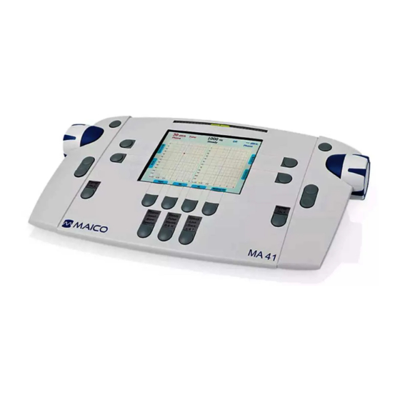
Minus (5) buttons on both sides of the instrument. The ergonomic design of the MA 41 makes it easy to control the dB level, signal presentation, and frequency adjustments with one hand. 5.1 Using the Control Panel of the MA 41 The main functions of the MA 41 are directly accessible by using the Function buttons which are located around the display. -
Page 17: Functionality Of Operating Elements
5.2 Functionality of Operating Elements The following table describes the main functions of each button for the tone and speech audiometry screens: Figure 3 - Control Panel MA 41 ... - Page 18 Operation Manual MA 41 Function button: to select left, right or both ears (10) Transducer selector button: to choose between Phones, Insert, Bone and, Speaker (only calibrated transducers are available) (11) Function button: function is displayed on the screen based on test screen...
-
Page 19: The Display Of The Ma 41
The display has an energy saving function; the backlight of the display is automatically dimed after approximately three minutes. Any action with the MA 41, such as pressing a button or rotating the dial, will immediately illuminate the backlight. 8100456 Rev.9... -
Page 20: Measurement Methods Of Audiometry
For hygienic reasons it is important to disinfect the ear cushions on the headphone between patients (see chapter 8). 6.1 Tone Audiometry The MA 41 supports tone audiometric testing methods. The following testing methods can be started in the tone audiometry mode and the results can be saved to the instrument. - Page 21 Operation Manual MA 41 6.1.1 Pure Tone Testing During pure tone audiometry, the patient’s hearing threshold is measured. Typically the threshold search begins with air conduction testing in the ear with better hearing. While viewing the tone screen the following settings will be displayed.
- Page 22 Operation Manual MA 41 dials) to present or interrupt the tone. The status LED for the stimulus mode button (8) will illuminate when the tone is presented. Follow your preferred procedure for the hearing threshold evaluation. Note: A warning prompt appears on the display in the event that the hearing level exceeds 100 dB .
- Page 23 Operation Manual MA 41 6.1.1.1 Masking Masking is required if there is a notable threshold difference between the left and right ears. It is possible for sound to be transmitted to both ears via bone conduction while testing the poorer ear. This is called “crossover.”...
- Page 24 Automatic Masking With the manual masking, as described before, the masking level should be adjusted every time you change the test signal level. The MA 41 has a tracking function for easy masking. Set the tone level and the masking level to a desired difference for effective masking.
- Page 25 Operation Manual MA 41 6.1.2 Bone Conduction Testing Place the bone conduction oscillator so that the flat, circular side of the transducer is placed on the mastoid, at the noticeable ledge of the cranial bone behind but not touching the pinna. The other side of the headband is placed in front of the opposite ear.
- Page 26 Operation Manual MA 41 6.1.5 Stenger The Stenger test is a test to confirm the presence of pseudohypacusis. During this test, two tones of the same frequency will be presented simultaneously to both ears, and only the louder tone will be perceived. Select HL to perform the Stenger test and select both ears (9).
-
Page 27: Speech Audiometry
6.2.1 Input Calibration The MA 41 must be calibrated to the particular speech test to ensure valid test levels. That means every time you change the speech test CD you must recalibrate the instrument. - Page 28 Operation Manual MA 41 6.2.2 Performing Speech Testing Use the function button for Speech on the right side of the tone screen (16) to switch to speech testing. The speech test screen will open, and the unit will default to the right ear and the level will be set to the default value.
- Page 29 Operation Manual MA 41 Make sure that the input signal is calibrated correctly, as described above. Select the test SRT, WRS or UCL with the function button (13). For the SRT test familiarize the patient with a closed set of spondaic words at a level loud enough for them to hear and understand.
- Page 30 Operation Manual MA 41 For the WRS test score, tally the correct words by pressing the frequency up (4) key and the incorrect words by pressing the frequency down (5) key. The next word will be played back automatically. The correct word is displayed green, while incorrect word is displayed red.
-
Page 31: Master Hearing Aid (Mha)
, was developed to provide a quick estimate of signal-to-noise ratio (SNR) loss. This test is incorporated into the MA 41, with selection made in the speech testing screen under the Wave file lists (11) or (15). The complete QuickSIN Speech-in-Noise Test manual, version 1.3 is provided in Appendix B. -
Page 32: Monitoring
Operation Manual MA 41 6.3 Monitoring All signals presented to the patient can be monitored by the examiner via a monitoring headset or the internal speakers. For this purpose, press the Monitor button (6) and the monitor screen will appear. -
Page 33: Documentation Of The Results
Operation Manual MA 41 6.5 Documentation of the Results All stored results can be directly printed via the USB printer. Make sure that a compatible printer is connected via the USB port (4) and the device is configured according to the connected printer settings; refer to menu settings in chapter 7.2. -
Page 34: Patient Management
Operation Manual MA 41 6.6 Patient Management The patient management option allows the results of the audiological tests to be stored on the SD memory card. The results can be reloaded at a later time to be reviewed, edited, or printed. Patients can be stored by a number ID or by entering the name and birth date. - Page 35 Operation Manual MA 41 session to the new patient number. To save the results to an existing patient, select a patient by the level controls and press the Save button. To save the current results to a new patient with a new patient name, press the button New Patient (15) and a screen appears to enter the patients last name, first name, ID and date of birth.
-
Page 36: Quick Reference Guide
Operation Manual MA 41 7 Quick Reference Guide 7.1 General Setup 7.1.1 Startup Settings Air conduction Pure tone on the right channel, left channel is switched off 30 dB tone Presenter mode 7.1.2 Transducer Selection Select the transducer to be used, headphones (Phones) or insert phones (Insert), by pressing the appropriate button (10). - Page 37 Operation Manual MA 41 7.2.2 Tone Audiometry Frequency Selection Use one of the two sets of frequency keys (4) or (5) to select the frequency. The maximum and minimum frequency depends on the transducer you have selected. Warble Tone Press the Test Signal button (12) to activate the warble tone. The LED will highlight Warble.
- Page 38 Operation Manual MA 41 7.2.3 Speech Audiometry To select speech audiometry, select Speech (16) and the test SRT or WRS (13). Use the frequency up (4) and down (5) key to select a word in the word list. For the WRS test the display shows the percentage of correctly repeated words.
-
Page 39: User Menu
Operation Manual MA 41 8 User Menu The User Menu enables the user to customize the device to meet their specific needs. Additionally, the menu allows the user to printout the results via USB printer, store the results as a PDF on an SD memory card or USB flash drive, and the ability to enter the patient list. - Page 40 Operation Manual MA 41 These menu items are available (Bold represents default setting): Frequency Settings Frequency Default Frequency Set (On/Off): Set default frequency if side, transducer or signal type has changed Frequency Roll Back: Frequency control jumps to 1,000 Hz if the highest and...
- Page 41 Operation Manual MA 41 Controller Assign ear side fixed to the left Signal Assignment or right controller; - Same, left dial controls level of the left ear, right dial the level of the right ear - Interchanged, left and right...
- Page 42 Operation Manual MA 41 Change Frequency Moves to next test frequency Store Properties After Store after storing a threshold (on) or stays on same frequency after storing (off) Change Level After Change in level after storing a Store threshold (stay at the same test...
- Page 43 Operation Manual MA 41 Diagram in Speech Diagram or Table Diagram Settings Test Number of Diagrams No audiogram, only the level in Tone Test and frequency, one combined audiogram or two separate audiograms for left and right Bone Lines On/Off, displays a dotted line,...
-
Page 44: Setup Date And Time
Operation Manual MA 41 8.1 Setup Date and Time Select Date/Time in the user menu by scrolling down with the left or right level control (1) and select Set Date/Time by using the stimulus presenter bar. The following screen will appear: Figure 15 - Date and Time Settings Set the date format to International or US by the function button (9). -
Page 45: Set Printer Settings
Operation Manual MA 41 8.2 Set Printer Settings Select the printer by turning the left or right level control (1) down. The color mode is automatically adjusted. If the color mode is wrong adjust the color mode as well. Jump to the field paper format by pressing the stimulus presenter bar several times and select A4 or Letter format by using the level controls. -
Page 46: Cleaning And Disinfection Recommendations
Recommendations for cleaning and disinfection of MAICO device presented in this document are not intended to replace or contradict policies in effect or procedures required for infection control at the facility. - Page 47 Operation Manual MA 41 until deemed safe by a MAICO certified service CAUTION technician. Do not use hard or pointed objects on the device or its accessories Use 70% isopropyl alcohol only on hard cover surfaces Discard single-use equipment after use! In case of re-use...
-
Page 48: Connection To The Pc
NOAH™ and the MAICO Database. The driver for the device will be installed automatically. Connect the MA 41 by USB cable to the PC and turn on the device. The required driver will be installed. Please follow the installation procedure. - Page 49 Operation Manual MA 41 Review the Audiometry Module User Manual for complete instructions of software use. This is located on the included CD and USB. 8100456 Rev.9 01/16...
-
Page 50: Technical Data
Operation Manual MA 41 11 Technical Data 11.1 Classification The MA 41 audiometer is an active, diagnostic medical product according to the class Ia of the EU medical directive 93/42/EEC. 11.2 Technical Data Standards: ANSI S3.6: Type 3B IEC 60645-1: Type 2 IEC 60645-2: Type B ISO 389 Acoustics –... - Page 51 Sound field speaker from Amp: Tones: - 10 dB ... 100 dB Speech: - 10 dB ... 90 dB Sound field speaker from MA 41: (using SP90 Speaker Kit) Tones: - 10 dB ... 90 dB Speech: - 10 dB ...
- Page 52 Operation Manual MA 41 Modulation: Pulse Tone: 0.25/0.5 s on time Warble Tone: 5% sinus frequency modulation, repetition rate 5 Hz Tests: Tone: HL, UCL Speech: SRT, WRS, UCL Patient Response: Handheld response switch Monitor: Build in monitor speaker, headset...
- Page 53 Operation Manual MA 41 Warm-up Time: Less than 10 min after power on Mode of Operation: Continuous 15 - 35 ̊ C / 59 - 95 ̊ F (operation) Environment Conditions: 5 - 50 ̊ C / 41 - 122 ̊ F (transport)
- Page 54 Operation Manual MA 41 13 1 Figure 19 – Connection Sockets of the MA 41 Connection sockets: Specification: 1: On/Off Power 2: Power (100 ... 240 V~ 50/60 Hz) Ethernet 3: Network USB 2.0 4: USB out USB 2.0 5: USB in = 500 ...
-
Page 55: Pin Assignment
Operation Manual MA 41 11.3 Pin Assignment Socket No. Connector Pin L Pin G Pin N (left) (top) (right) DC socket L (Live) G (Ground) N (Neutral) Rated current international: 250 V/2,5 A LAN Ethernet Socket No. TX + Transmit Data... -
Page 56: Warranty, Maintenance And After-Sales Service
The MA 41 may be repaired and serviced only by your dealer or by an authorized service center. We urgently advise you against attempting to rectify any faults yourself or commissioning non-experts to do so. -
Page 57: Safety Regulations
Consult operating instructions before using this device. 13.1 Electrical Safety The MA 41 audiometer is a B patient applied part according to international standard IEC 60601-1 (EN 60601-1). The instruments are not intended for operation in areas with an explosion hazard. -
Page 58: Warnings And Statements
13.5 Warnings and Statements No modification of this equipment is allowed. Maico will make available instructions and diagrams to repair devices that it deems appropriate to be repaired in the field. No adverse effects have been reported from the materials used in this device based on 50 plus years of use with many different patient populations. -
Page 59: Appendix A: Checklist For Subjective Audiometer Testing
Operation Manual MA 41 Appendix A: Checklist for subjective Audiometer Testing - Clean the ear and head cushion! Instrument:........- Untangle all lines when necessary! - Are the headphone cushions in good condition? Manufacturer:…........ If not replace. - Are plugs and leads in good condition/ undamaged? Serial No.:......... -
Page 60: Appendix B: Calibration Values And Maximum Levels
Operation Manual MA 41 Appendix B: Calibration Values and Maximum Levels Calibration values and Max Levels: Headphone DD45 Coupler IEC 60318-3, Force 4-5 N, ANSI and IEC Frequency Tone Max Tone Max NBN RETSPL RETSPL [Hz] dB re 20µPa dB re 20µPa 47.5... - Page 61 Operation Manual MA 41 Calibration values and Max Levels: Headphone TDH39 Coupler IEC 60318-3, Force 4-5 N, ANSI and IEC Frequency Tone Max Tone Max NBN RETSPL RETSPL [Hz] dB re 20µPa dB re 20µPa 45.0 49.0 25.5 29.5 11.5 15.5...
- Page 62 Operation Manual MA 41 Calibration values and Max Levels: Headphone Holmco 8103 Coupler IEC 60318-3, Force 4-5 N, ANSI and IEC Frequency Tone Max Tone Max NBN RETSPL RETSPL [Hz] dB re 20µPa dB re 20µPa 39.5 43.5 25.0 29.0 18.5...
- Page 63 Operation Manual MA 41 Calibration values and Max Levels: Headphone HDA 300 Ear simulator IEC60318-1 with adapter, Force 8.8 N ± 0.5 N, ANSI and IEC Frequency Tone NBN RETSPL Max Tone Max NBN RETSPL [Hz] 27.0 31.0 20.0 24.0 12.0...
- Page 64 Operation Manual MA 41 Calibration values: Insert phone IP30 Reference equivalent threshold sound pressure level Tone IEC NBN IEC Tone 60318-5 Frequency 60318-5 Max Level Max Level [Hz] RETSPL RETSPL dB re dB re 20µPa 20µPa 26.0 30.0 14.0 18.0...
- Page 65 Operation Manual MA 41 Calibration values: Bone conductor Radioear B71 / B71W Force: 4.9 ... 5.9 N Mastoid placement Frequency Reference equivalent Air radiation Max level [Hz] threshold force level for tone ISO 389 - 3 ANSI S3.6 mean/max Tone [dB] (re 1µN)
- Page 66 Operation Manual MA 41 Calibration values: Bone conductor Radioear B81 Force: 4.9 ... 5.9 N Mastoid placement Frequency Reference equivalent Air radiation Max level [Hz] threshold force level for tone ISO 389 - 3 ANSI S3.6 mean/max Tone [dB] (re 1µN) [dB] (re 1µN)
- Page 67 Operation Manual MA 41 Calibration values: Sound field (0 degree incidence) Reference equivalent threshold sound pressure level and maximum hearing levels For Canton CD 220 / MAICO SBC speaker ISO 389 – 7 and ANSI S3.6-1996 Frequency Tone Max level...
-
Page 68: Appendix C: Emc Compatibility
MA41. Install and operate the MAICO MA41 according to the EMC information presented on this page and the next 4 pages. The MAICO MA41 has been tested for EMC emissions and immunity as a standalone instrument. Do not use the MAICO MA41 adjacent to or stacked with other electronic equipment. - Page 69 Guidance and Manufacturer’s Declaration - Electromagnetic Emissions The MAICO MA41 is intended for use in the electromagnetic environment specified below. The customer or the user of the MAICO MA41 should assure that it is used in such an environment. Emissions Test...
- Page 70 Recommended Separation Distances between Portable and Mobile RF Communications Equipment and the MAICO MA41 The MAICO MA41 is intended for use in an electromagnetic environment in which radiated RF disturbances are controlled. The customer or the user of the MAICO MA41 can help prevent...
- Page 71 Operation Manual MA 41 Guidance and Manufacturer’s Declaration - Electromagnetic Immunity The MAICO MA41 is intended for use in the electromagnetic environment specified below. The customer or the user of the MA41 should assure that it is used in such an environment.
- Page 72 If the measured field strength in the location in which the MA 41 is used exceeds the applicable RF compliance level above, the MA 41 should be observed to verify normal operation. If abnormal performance is observed, additional measures may be necessary, such as re- orienting or relocating the MA 41.
- Page 73 Operation Manual MA 41 Specifications are subject to change MAICO Diagnostics GmbH Sickingenstr. 70-71 10553 Berlin Germany Tel.: + 49 30 / 70 71 46-50 Fax: + 49 30 / 70 71 46-99 E-mail: sales@maico.biz Internet: www.maico.biz 8100456 Rev.9 01/16...
Need help?
Do you have a question about the MA 41 and is the answer not in the manual?
Questions and answers
I am new to this audiometer and I need to use it ASAP. Can you call me to review it 272-800-8539