Table of Contents
Advertisement
Quick Links
1.
Home
Manual, August 2005
Introduction
1.1. CAMAG ADC2
The Automatic Development Chamber (ADC2) permits repro-
ducible chromatogram development without the need for con-
stant monitoring by the user. The ADC2 is shipped with
EquiLink, RS232 cable and built-in interface for connecting to a
computer with winCATS from which the instrument can be run
but it can be used in Stand-Alone mode too.
By means of ADC2, developing of HPTLC chromatograms will
be reproducible. The user is free from any process monitoring.
The user decides whether and how to precondition the plate,
pre-selects the distance to be migrated by the solvent system
and the drying parameters.
Development proceeds automatically and under controlled con-
ditions. A CCD-sensor monitors the progress of the solvent
front; the distance covered and the time elapsed are continu-
ously displayed. On completion of development, the HPTLC
plate is dried with air and finally stays safely protected in the
chamber until removed by the user.
If used in Stand-Alone mode all method parameters are en-
tered via the keypad. Ten complete development programs can
be saved in nonvolatile memory and started at will without PC-
control.
HPTLC plates with a thickness of up to 2.5mm can be used in
the ADC2. If using aluminum foils it is mandatory to utilize a
special foil holder # 115.8363.
The ADC2 controlled by the software winCATS >Planar Chro-
matography Manager< permits full control of the development
process by monitoring and reporting all parameters including all
TLC steps of an analysis, i.e. definition of plate material, sample
application, derivatization, development and evaluation. All data
are handled in a GMP/GLP compliant environment. With the
appropriate winCATS option, the ADC2 can be used in a 21
CFR Part 11 compliant environment.
Information on how to install the ADC2 EquiLink is available in
the comprehensive electronic help system and the interactive
tutorial supplied with winCATS.
ADC 2
Page 1
Advertisement
Table of Contents

Related Manuals for CAMAG ADC2


Summary of Contents for CAMAG ADC2
- Page 1 HPTLC plates with a thickness of up to 2.5mm can be used in the ADC2. If using aluminum foils it is mandatory to utilize a special foil holder # 115.8363. The ADC2 controlled by the software winCATS >Planar Chro- matography Manager<...
- Page 2 • The ADC2 must only be used by properly trained laboratory staff. • It’s not allowed to work with ADC2 in rooms with danger of explosions. • The instrument contains highly sensitive electronic and me- chanic parts;...
- Page 3 ADC 2 • Use a humid cloth for cleaning the instrument surface. Do not employ aggressive detergents. • Protect yourself and the instrument from electrostatic shock, which can cause damage to the electronic parts. • Only authorized personnel may open the instrument. Service and repair is only to be performed by trained specialists.
-
Page 4: Parts Supplied
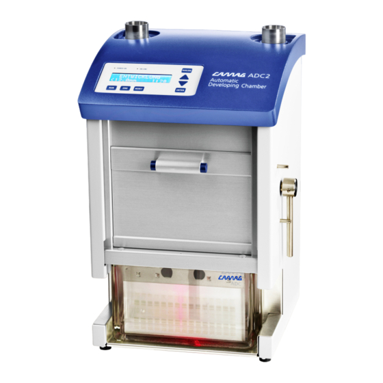
ADC 2 1.3. Parts supplied Part # Parts supplied 022.8350 ADC2 Device for 100 – 240 V, 50 / 60 Hz, 20W 140.8350 Tool kit, comprising: 022.5261 Twin Trough Chamber 672.0059 Exhaust tube 115.8352 Plate holder (old) - New magnet holder # 022.8372 941.0006 Saturation pads (pack of 25) - Page 5 Remove carefully the fixation under the Drying module. For shipment, the Twin Trough Chamber has been securely positioned below the bottom of the instrument. Fig. 1: The ADC2 instrument Manual, August 2005 Page 5...
-
Page 6: Installation Environment
ADC 2 Fig. 2: The instrument ADC2 (opening the front door) 2.2. Installation environment The place for installation must meet the following requirements: Bench space Width 320mm Depth 320mm without Humidity Option Depth 460mm with Humidity Option (additional for tubes 250mm) Height 520mm Weight 18.5kg... -
Page 7: Conditions For The Installation
ADC 2 Further requirements: • Do not place the instrument in a location where the tempera- ture significantly changes (e.g. under an air conditioning duct or by a window). Significant changes in temperature will af- fect the performance of the unit. •... -
Page 8: Mains Connection
Power switch and mains connection with fuse box. 2.5. Connection to the PC The CAMAG ADC2 is shipped with a 9-pin RS 232 interface cable for connection to the PC. If you wish to use the instrument controlled by winCATS: Connect the cable to the instrument and to a free COM-port of the PC to enable data transfer. - Page 9 ADC 2 2.6. Mounting the exhaust tube The shipment contains an exhaust tube, witch can be slipped onto the “black” air outlet fig.4, permitting exhaust solvent vapor to be directed into a fume hood or other vent. Connecting Sleeve # 672.0058 Fig.
-
Page 10: Checking System Functions
For error messages see chapter 6.8. 3.2. Checking system functions Switch on the instrument. The ADC2 will now show the installed firmware version and perform the following checks and tasks: 1. Initializing the drying module. - Page 11 Home The plate-holder is designed to attach and handle the HPTLC plates in the ADC2. When inserting a plate into the plate holder the TLC layer side must be facing the user (the text ‘LAYER’). Fig. 5: Insert TLC plate in plate-holder Fig.
- Page 12 ADC 2 Note: Clamping foils works similar to that of HPTLC plates; the two edges of the foil, left/right, must be inserted underneath the respective down holders, fig. 7. Home Fig. 7: Mounting a foil into a foil-holder 4.2. Drying module and plate lift To attach the plate or foil holder into the drying-module approach the holder to the lift magnets as shown in fig.
- Page 13 9. When the Twin Trough Chamber has been positioned inside the ADC2 make sure the chamber is touching the two stoppers at the back, otherwise chromatography cannot be started. The ‘CAMAG’ label of the Chamber should normally face the user;...
- Page 14 ADC 2 4.3.1. Use of saturation pad: When a saturation pad is needed, make sure it has been in- serted in the right position, i.e. the fold of the pad is contacting the bottom of the Twin Trough Chamber while the shorter side is lying on the bulge of the chamber, fig.
- Page 15 Home The inlet reservoirs for developing (mobile phase) and precondi- tioning solvents are located on top of the ADC2. The left inlet is used for developing solvent and the right inlet for precondition- ing solvent. The volume of developing solvent should be 10ml, the preconditioning volume 25ml.
- Page 16 ADC 2 4.5. Display and function of keys Control lamps The control lamps in the display indicate the following status: • POWER ON: this lamp is lit when the instrument is switched • ON LINE: this lamp is lit when the instrument is ON-LINE with PC / winCATS.
- Page 17 ADC 2 RESET Resets and re-initializes the instrument. The current method is interrupted but all parameters remain in memory. Shows the selection of stored methods. Use the arrow keys 5 or 6 to select a method to start. Press ENTER to start the selected method or DIALOG to change the parameters of the actual method.
-
Page 18: Stand-Alone Operation
To save a winCATS method in the instrument follow the proce- dure outlined in the ADC2 section of the winCATS help. 5.1. Procedure for Stand-Alone start: Home Prepare the instrument for development. -
Page 19: Resetting The Instrument
ADC 2 5.3. Procedure for saving a changed method: Select the parameter group Save method or press the END key after having changed the parameters. Select the memory position to save the new method by means of the 5 or 6 key. Press ENTER to confirm position and save the parameters. - Page 20 Text Description Shows the actual firmware FW V: 1.00.01 version at startup. ************* Display during initialization of ADC2 CAMAG at power up. * ADC2 SYSTEM * The system was properly initialized ADC2 and is waiting for a development. SYSTEM READY Selection of a stored method.
- Page 21 ADC 2 6.2. The Normal operation mode dialog POWER ON SYSTEM READY Method RUN ? stack Repeat last ENTER ? method Select END ? manual functions Show temperature & DOWN ? rel. humidity Boxes with two lines on both sides include another diagram, shown in the next pages.
- Page 22 ADC 2 6.3. The method stack dialog To enter the method selection dialog (Method stack), press the RUN key when the instrument display shows “System ready”. THIS METHOD ? METHOD XX Increment / DOWN ? decrement method # Back to Start selected Normal ENTER ?
- Page 23 ADC 2 6.4. The Dialog mode To enter this parameter type selection dialog, press the Home DIALOG key when the instrument display shows the name of the method to be edited (in the method stack dialog). THIS DIALOG ? DIALOG TYPE Increment / DOWN ? decrement di-...
- Page 24 ADC 2 6.5. The Parameters Input dialog To enter this parameter input dialog, press the ENTER key when the display shows the name of the parameter type to be edited (in the Dialog mode). ENTER GLOBALS PLATE TYPE ENTER PARAMETERS CONTROL HUMIDITY (TIME) TANK SATURATION TIME PLATE PCOND.
- Page 25 ADC 2 6.6. The Manual functions dialog To enter the Manual function selection dialog, press the END key when the instrument display shows “System ready”. Home THIS FUNCTION ? MANUAL FUNCTION Select function DOWN ? Back to Start selected ENTER ? function Normal operation...
- Page 26 ADC 2 6.7. The Setup dialog To enter the Setup dialog, hold down the DIALOG key wile switching on the instrument. DIALOG & POWER ON All keys except SHOW ENTER FIRMWARE VERSION ENTER RESET SELECT BAUDRATE ENTER RESET SELECT LANGUAGE ENTER RESET SELECT LCD...
-
Page 27: Error Messages
The changing of positions of the humidity module valve was lasting too long, i.e. valve is locked or dirty. There is no solvent (mobile phase) in the chamber. There is no TLC plate in the ADC2. Humidity / temperature sensor damaged, bad con- nection or failed. - Page 28 Hold down the DIALOG key and press the RESET key. Release the RESET key, then release the DIALOG key. The display will now show ADC2 Vx.xx.xx Setup Mode, where x.xx.xx is the actual firmware version of the ADC2. Press the ENTER key to start the Setup dialog.
-
Page 29: Set Display Language
ADC 2 7.2.2. Set display language Start the setup dialog according to the procedure above. The display now shows the current baud rate. Press the ENTER key to move on to the language selection display. The current language setting is displayed. Press the key to change the setting. -
Page 30: Replacing Fuses
ADC 2 7.3. Replacing fuses Procedure: First disconnect the power cord from the mains connection of the instrument. Unlock the fuse holder over the main socket with help of a small screwdriver. Press it on both sides of the holder into the recess. -
Page 31: Technical Data
ADC 2 Technical data Main power 100 – 240 V; 50 / 60 Hz; 20 W Home connections Drying module drive Stepper motor 1600 steps/rev., 160 steps = 0.1mm Positioning with acceleration ramp Lift drive Stepper motor 1600 steps/rev, 5 steps = 0.1mm Positioning with acceleration ramp Dimensions Width 330mm, depth 330mm, height 520mm... -
Page 32: Appendix A Option Humidity Control (022.8360)
General / saturated salt solution Home The desired humidity is adjusted in the ADC2 by means of a saturated salt solution (not included in shipment). Alternatively it is possible to achieve very dry atmospheric conditions if a mo- lecular sieve (not included in shipment) is used instead. - Page 33 20 to 21°C reduces the relative humidity by 5% down to 70%. A constant temperature is thus necessary for reaching optimal humidity constancy. The salt solution should in any case have the same temperature as the ADC2, which, especially with re- cently manufactured salt solutions is generally not immediately the case.
-
Page 34: Installation
Fig.13: Ventilation valve module: 1= fixation screws. For adapting the Humidity Control device, four screws (1) are provided to fix it on the back of the ADC2; they are used as fixation of the ventilation valve module. The ventilation valve module is mounted on a holding plate that has to be placed in the position over the four screws and tightened. - Page 35 (grey socket) to the “grey” socket of the ventila- tion valve! WARNING: Make sure to connect these hoses correctly, because you would fill the ADC2 with salt solution in case of a wrong connection! (See fig. 15.1) Manual, August 2005...
- Page 36 ADC 2 Fig. 15.1 The two sockets directed down on the ventilation valve mount are for exhaust and air supply. The exhaust tube has to be slipped onto the “black” socket, fig. 15.2. sleeve # 672.0058 Fig. 15.2: Humidity module: 1 = center hose, 2 = top cover, 3 = outside hose, 4 = exhaust hose Warning! Never insert your fingers into the sockets! Manual, August 2005...
- Page 37 ADC 2 Preparation of saturated salt solution 3.1. Magnesium chloride Hexahydrate (rH at 20°C 33%) Add 900g MgCl2 hexahydrate into the gas wash bottle. Add 200 mL distilled water and heat it up to 40-50 C° under stirring. Set the final volume to 800 mL. Cool down after 10 minutes to room temperature.
- Page 38 A good example is shown in the graphics below: Home °C [Minutes] Fig.16: Measurement of the relative humidity in the ADC2 at start of the humidity con- trol. Used salt: Potassium thiocyanate, relative humidity in the lab approx. 29%. 24.5 °C 23.5...
- Page 39 ADC 2 Additional measurement values Several approaches have been made to quantitatively measure the effective humidity on a HPTLC plate. It has been proven that by means of this principle for humidity control, the activity of the plate can be controlled reproducibly. The figure below shows 4 different measurements and reated transfer times from dry to humid and vice versa.
- Page 40 ADC 2 Manual, August 2005 Page 40...
Need help?
Do you have a question about the ADC2 and is the answer not in the manual?
Questions and answers