Table of Contents
Advertisement
Advertisement
Table of Contents
Troubleshooting

Related Manuals for CAMAG ATS 4


Summary of Contents for CAMAG ATS 4
- Page 1 INSTRUCTION MANUAL AUTOMATIC TLC SAMPLER 4...
-
Page 2: Table Of Contents
Introduction Content Introduction ............................ 3 CAMAG automatic TLC sampler 4 (ATS4) .................. 3 Precautions ..........................3 Parts supplied with the instrument .................... 5 Spare parts/consumables ......................6 Unpacking/Installation ........................7 Unpack the instrument ......................7 Remove turret transport lock ......................7 Remove the table transport lock ...................... - Page 3 Introduction Reset the pre-dosage position ....................18 Clean the rinsing unit ......................18 Manual control of the rinsing unit ................... 19 Entering the syringe and needle type ..................19 Stopping or resetting the instrument ..................19 4.10 Mounting the baffle bridge with septum foil ................19 Maintenance and troubleshooting .....................
-
Page 4: Introduction
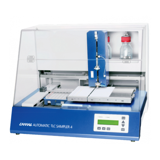
1 Introduction 1.1 CAMAG automatic TLC sampler 4 (ATS4) The CAMAG Automatic TLC Sampler 4 is a fully automatic sample application device for use in qualitative, quantitative and preparative Thin-layer chromatography. The system consists of the instrument with interface, computer and software from which the instrument is programmed. - Page 5 Only authorized personnel may open the instrument. Service and repair is only to be performed by trained specialists. Use spare parts and consumables supplied by CAMAG only. The warranty is voided if parts from other sources are used. Check the service manual before you start service to reduce product-specific risks •...
-
Page 6: Parts Supplied With The Instrument
Introduction • Carry out all safety checks and the preventive maintenance as recommended by the manufacturer in order to assure your personal safety and the full functionality of the instrument. Have an authorized service specialist perform any service not described by this manual •... -
Page 7: Spare Parts/Consumables
Introduction 1.4 Spare parts/consumables Part no Description 022.7450 Dosing syringe starter kit for ATS4 consisting of: 695.0053 25 µL Dosing syringe without needle 695.0046 Syringe needle for spray-on application 695.0047 Syringe needle for contact application 115.7402 Heated spray nozzle, pre-assembled 695.0043 100 µL Dosing syringe without needle 695.0053... -
Page 8: Unpacking/Installation
Unpacking/Installation 2 Unpacking/Installation 2.1 Unpack the instrument Observe the environmental requirements (below) when setting up the instrument. Carefully take all components listed in the shipping list as well as accessories out of the packing. Make sure the shipment is complete. Before taking the instrument out of the container the upper foam packing must be removed. -
Page 9: Installation Environment
Unpacking/Installation Fig. 2: Table transport lock Do not dispose the transport lock – keep them at an appropriate place for further use. 2.2 Installation environment The place for installation should meet the following requirements: Bench space Width 630mm (add space for cables approx. 100mm) Depth 530mm Height 500mm Add adequate space for a PC next to the instrument. -
Page 10: Installation
Unpacking/Installation • Do not place the instrument near equipment that generates intense magnetic fields such as electric welding equipment, high frequency furnaces, pole transformers, etc. • Protect the instrument from excessive dust. • Connect the instrument to power lines that are free from sudden changes or voltage fluctuations. -
Page 11: Gas/Air Connection
Unpacking/Installation Fig. 3: 1 = waste bottle and 2 = rinsing bottle Gas/air connection Connect the supplied pressure tubing to the quick connection pressure inlet on the backside of the instrument. Connect the other end of the tubing to the gas supply. If the outlet of your gas supply does not fit, the N2/compressed air connection kit allows connection to standard ¼”... -
Page 12: Mains Connection
Unpacking/Installation • Turn the syringe into a position where the side connector (3) faces the front of the instrument. Fix the position of the syringe with the two knurled screws (4) (tighten equally). • DO NOT use force when tightening the knurled screws. •... -
Page 13: Connection To The Pc And Installation
Fig. 5: Connections – 1=RS232 Interface, 2=Power switch, 3=Mains connection with fuse box Connection to the PC and installation The CAMAG automatic TLC sampler 4 is shipped with a 9-pin interface cable for connection to the PC. Connect the cable to the instrument and to a free COM-port of the PC to enable data transfer. -
Page 14: Set Display Language
Unpacking/Installation Set display language Start the user dialog according to the procedure above. The display now shows the current baud rate. • Press the ENTER key to move on to the language selection display. The current language setting is displayed. •... -
Page 15: Getting Started
Getting started 3 Getting started 3.1 Starting the system Switch on the instrument. The ATS4 will now perform the following checks and tasks: 1. Checking memory for data loss. Parameters (methods) are stored in memory for more than 7 days. 2. -
Page 16: Loading A Tlc-Plate/Foil
Getting started 3.4 Loading a TLC-plate/foil • Move the plate lift lever (1) situated on the right side of the plate stage to the rear in order to lower the right part of the stage. • Flip the front ledge (2) of the stage down (forward) making the plate stage freely accessible. - Page 17 Getting started For TLC foils which might not lay flat on the stage at the positioning pins a down-holder is designed. It is to be used according to below figure and may be left in place if only foils are being used. The positioning of foils is similar to that of TLC-plates.
-
Page 18: Manual Operation
Manual operation 4 Manual operation 4.1 Display and function keys Control lamps The control lamps in the display indicate the following status: • POWER ON: this lamp is lit when the instrument is switched on. • ON LINE: this lamp is lit when the instrument is ON-LINE to the PC or is communicating with the PC. -
Page 19: Aborting An Application In Progress
Manual operation • Press the RUN key • The most recently used method is displayed. With the and keys you can select another locally saved method. • Press the ENTER or RUN key to start the application. If no method is locally saved the message “MEMORY EMPTY” is displayed for 2 second. Then the instrument goes to ready position. -
Page 20: Manual Control Of The Rinsing Unit
4.10 Mounting the baffle bridge with septum foil The instrument is usually equipped with a baffle bridge without septum foil support. Optionally available is the baffle bridge with septum foil support (CAMAG part number 022.7460). This bridge is recommended when using micro titer plates or vials not equipped with septa. - Page 21 Manual operation Fig. 9: Sample rack, baffle bridge with septum foil and rinsing unit 1 = baffle bridge with septum foil, 2 = sample rack for 2 mL sample vials 12x32 mm, 3 = septum foil, 4 = septum holder, 5 = attachment screws. •...
-
Page 22: Maintenance And Troubleshooting
Do not expose the plunger to boiling water. • Plungers, needles and syringe bodies are exchangeable. CAMAG recommends exchanging those parts regularly. Check the CAMAG Maintenance Data Sheet for information of replacement cycles 5.2 Adjusting the spray gas pressure Spray gas flow is controlled by a gas pressure regulator, factory adjusted to 0.5 bar. It may be suitable to increase this pressure to achieve better spray quality when using highly viscous liquids. -
Page 23: Septum Puncher
5.4 Septum puncher Prior to using the instrument check the state of the septum punch. A bent or broken septum punch will damage the needle To get correct results and keep the instrument in god condition, CAMAG recommends following below point: •... -
Page 24: Replacing Fuses
Maintenance and troubleshooting • Screw the new septum punch into position and tighten it. • Re-install the baffle bridge. • Mount the syringe and the sample rack 5.6 Replacing fuses • Switch off the instrument. • Disconnect the power cord from the electrical inlet of the instrument. •... - Page 25 Maintenance and troubleshooting The side connector or another connection such as the lid of the waste bottle is not tight Action: Check side connector and tighten it, check lid of waste bottle for tightness The vacuum pump or the valve for emptying the waste container is defective Request service for vacuum pump or valve.
-
Page 26: Service Maintenance
The instrument may only be serviced by authorized technicians who have been properly trained. In addition to the aforementioned user maintenance, CAMAG strongly recommend that maintenance be performed at least once each year by CAMAG authorised service personnel. Regular service and maintenance will ensure that the instrument performs according to CAMAG specifications. - Page 27 Maintenance and troubleshooting Drive problems (mechanical or electrical) Rack drive: End switch was active during Call your service contact 1124 movement 1125 Stage drive: ditto Call your service contact 1126 Turret drive: ditto Call your service contact 1127 Lift drive: ditto Call your service contact 1128 Syringe drive: ditto...
-
Page 28: Technical Data
Technical data 6 Technical data Power connections 85 – 250 V∼ 47 – 63 Hz 60 VA Dosing syringe Choice of 10, 25 or 100 µL, gas-tight with side port Dosing volume 100 nL to 1 mL in steps of 100nL Syringe drive Stepper motor 1600 steps / rev.: 100nL = 960 steps for 10µL syringe... -
Page 29: Maintenance Data Sheet
Maintenance data sheet 7 Maintenance data sheet CAMAG Maintenance data sheet ATS 4 October 2013/UB Purpose The maintenance data sheet informs about maintenance interval of the respective instrument as well as the proposal for IQ/OQ interval if applicable. In addition, it identifies consumable parts with the respective replacement cycle. - Page 30 49 30 516 55 50 · Fax 49 30 795 70 73 · E-Mail: infoberlin@camag.com CAMAG Scientific Inc. (USA) · 515 Cornelius Harnett Drive · Wilmington, NC 28401 Telephone 800 334 3909 · Fax 910 343 1834 · E-Mail: tlc@camag.com www.camag.com...
- Page 32 Notes: __________________________________________________________________________________ __________________________________________________________________________________ __________________________________________________________________________________ __________________________________________________________________________________ __________________________________________________________________________________ __________________________________________________________________________________ __________________________________________________________________________________ __________________________________________________________________________________ __________________________________________________________________________________ __________________________________________________________________________________ __________________________________________________________________________________ __________________________________________________________________________________ __________________________________________________________________________________ __________________________________________________________________________________ __________________________________________________________________________________...
- Page 33 Notes: __________________________________________________________________________________ __________________________________________________________________________________ __________________________________________________________________________________ __________________________________________________________________________________ __________________________________________________________________________________ __________________________________________________________________________________ __________________________________________________________________________________ __________________________________________________________________________________ __________________________________________________________________________________ __________________________________________________________________________________ __________________________________________________________________________________ __________________________________________________________________________________ __________________________________________________________________________________ __________________________________________________________________________________ __________________________________________________________________________________...
Need help?
Do you have a question about the ATS 4 and is the answer not in the manual?
Questions and answers