Table of Contents
Advertisement
Advertisement
Chapters
Table of Contents

Related Manuals for Life Fitness Aspire ASPX-SL


Summary of Contents for Life Fitness Aspire ASPX-SL
- Page 1 Aspire Cross-Trainer ASPX-SL, PF-ASPX Assembly Instructions 1021561-0001 REV AA...
- Page 3 Latin America and Caribbean* Spain Hong Kong Life Fitness, LLC Life Fitness IBERIA Life Fitness Asia Pacific LTD 10601 W Belmont Ave C/Frederic Mompou 5,1º1ª 26/F, Global Trade Square Franklin Park, IL 60131 U.S.A. 08960 Sant Just Desvern Barcelona...
- Page 4 User and Service Documents Link https://lifefitness9512.zendesk.com/hc/en-us https://www.lftechsupport.com/web/document-library/documents Additional information is available online using the links above. أ علاه إل ر إبط باستخدإم إ لإ ن تر نت على إضافية معلومات تتوفر 点击上面的链接可在线获取更多信息。 Flere oplysninger er tilgængelige online gennem linket ovenfor. Bijkomende informatie is online beschikbaar via bovenstaande link.
-
Page 5: Table Of Contents
Copyright 2022, Life Fitness, LLC. All Rights Reserved. Life Fitness, Hammer Strength, Cybex, ICG and SCIFIT are registered trademarks of Life Fitness, LLC and its affiliated companies and subsidiaries. Disclaimer: Images and specifications are current as of the date of publication and are subject to change. -
Page 6: Getting Started
• Life Fitness Family of Brands does not warrant nor guarantee that component parts used in the manufacture of products offered under the Life Fitness Family of Brands are latex-free. Users of these products must take all necessary precautions to prevent accidental contact that could lead to an adverse latex reaction. - Page 7 • Allow LCD consoles to “normalize” with respect to temperature for one hour before plugging the unit in and using. • When the product is not in use, Life Fitness recommends unplugging the product. Disconnect from the electrical outlet when not in use, and before putting on or taking off parts.
-
Page 8: Consignes De Sécurité
Consignes de Sécurité Veuillez lire toutes les instructions avant usage. ATTENTION : Toute modification apportée à cet équipement pourrait en annuler la garantie. AVERTISSEMENT : Une utilisation incorrecte ou excessive de l'appareil peut entraîner des blessures. Life Fitness Family of Brands Recommande VIVEMENT aux utilisateurs de passer un examen médical complet avant d'entamer un programme d'entraînement, et tout particulièrement dans les cas suivants : antécédents familiaux d'hypertension (pression sanguine trop élevée) ou de pathologies cardiaques, utilisateurs de 45 ans ou plus, tabagisme, hypercholestérolémie (taux de cholestérol sanguin trop élevé), obésité, absence d'exercice... - Page 9 à la clientèle. Nous vous en fournirons de nouvelles. Les étiquettes d’avertissement sont expédiées avec les appareils et doivent être installées avant utilisation de ces derniers. Life Fitness Family of Brands n’est pas responsable des étiquettes manquantes ou endommagées.
-
Page 10: Where To Place And How To Stabilize The Cross-Trainer
Where to Place and How to Stabilize the Cross-Trainer Read the entire manual before setting up the cross-trainer. After following all Safety Instructions, move the unit to the location where it will be used. Allow 1 ft. (0.3 m) of clearance in front of the cross-trainer and at least 2 ft. (0.6 m) on the side. -
Page 11: Electrical Power Requirements (Applicable For Units Using External Power Supply)
The SL Console is powered by a rechargeable 6-volt battery. Check the battery by pressing the GO button. The console should beep and light up. The console will display the Life Fitness logo. If a prompt doesn’t appear, mount the unit and begin pedaling. The console should light up and programming a workout should be possible. Pedal for 10 - 20 minutes at 50 rpm or faster during a workout for optimum battery charging. -
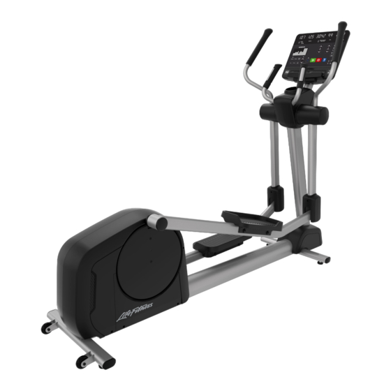
Page 12: Product Overview
2. Product Overview Product Features Item Description Qty. Console Contact Heart Rate Sensors Cup Holder Pedals Leg Levelers Transport Wheels NOTE: SL Console shown for reference. Connections The following connection receptacle is located at the front of the cross-trainer. Item Description Coaxial Connection Power Input... -
Page 13: Assembly
3. Assembly Hardware Hardware Pack 1 Used to install: Monocolumn, Monocolumn Lower Shrouds, and Rear Clevis Covers Item Description Qty. Grommet Screw, M4.2 x 19, Phillips Pan Head Locknut Hardware Pack 2 Used to install: Pedal Levers Item Description Qty. Washer, 25mm ID Washer, Flat Screw, M8 x 20, Hex Head... -
Page 14: Tools Required
Hardware Pack 3 Used to install: Console and Rear Console Shroud Item Description Qty. Grommet Screw, M4.2 x 19, Phillips Pan Head Screw, M5 x 14, Phillips Pan Head Tools Required • 7 mm Allen wrench • 13 mm Socket wrench with Extension •... -
Page 15: Assembly Procedure
Assembly Procedure Two people are recommended for this procedure. TIP: Read and understand all instructions thoroughly before assembling this unit. Check all items carefully. If there is damage, see the Customer Service section of this manual for proper procedure to return, replace, or reorder parts. Install Monocolumn 1. - Page 16 4. Install locknuts to screws securing monocolumn to main frame assembly. NOTE: Make sure top plate is flush with bottom plate. Item Description Qty. Locknut Screw, M8 x 1.25 Hand tighten hardware. NOTE: Install locknuts in the order shown below. 5.
- Page 17 6. Tighten hardware in the following order: a. Pivot bolt and locknut to 35 ft-lb (47.5 Nm). b. Two side locknuts to 20 ft-lb (27Nm). c. Four top locknuts to 20 ft-lb (27Nm). Install Lower Shrouds and Communication Port 1. Press grommets into right and left side of main frame assembly. 2.
- Page 18 4. While holding communication port in place, install screws securing left lower shroud to main frame assembly using a Phillips screwdriver. NOTE: Install rear screw first to assist in aligning shroud. Item Description Qty. Left Lower Shroud Main Frame Assembly Screw, M4.2 x 19, Phillips Pan Head Grommet Hand tighten hardware.
-
Page 19: Washer, 25Mm Id
Install Left Pedal Lever 1. Rotate left pedal lever so it aligns with crank arm. Item Description Qty. Pedal Lever Crank Arm 2. Install screw and washers securing left pedal lever to crank arm using a 13mm wrench with extension. Item Description Qty. -
Page 20: Grommet
2. Install screw and grommet securing rear clevis cover to rocker arm using a Phillips screwdriver. Item Description Qty. Rear Clevis Cover Rocker Arm Screw, M4.2 x 19, Phillips Pan Head Grommet Tighten hardware to 13 in-lb (1.5 Nm). 3. Slide rubber gasket down rocker arm. Adjust gasket so it is flush with top of covers and there is no visible gap between gasket and covers. - Page 21 Install Console Install screws securing console to console support weldment using a Phillips screwdriver. NOTE: Use the hook on top of the console support weldment to aid in console installation. Item Description Qty. Console Console Support Weldment Screw, M5 x 14, Phillips Pan Head Ground Screw (see Note) Tighten hardware to 16.8 in-lb (1.9 Nm).
-
Page 22: Specifications
4. Specifications Product Specifications Heavy / Commercial EN ISO 20957 Class SA Designed Use Models: ASPX-SL, PF-ASPX Maximum User Weight 400 lbs. / 181 kg Drive Type Generator Pedal Speed Range 2.5 - 14 mph (4 - 22.5 kph) Resistance Levels Power Requirements See Electrical Power Requirements Section Patented Lifepulse ™... -
Page 23: Service And Technical Data
5. Service and Technical Data Preventive Maintenance Tips NOTE: Safety of the equipment can be maintained only if the equipment is examined regularly for damage or wear. Keep the equipment out of use until defective parts are repaired or replaced. Pay special attention to parts that are subject to wear, as outlined below. -
Page 24: Preventative Maintenance Schedule
Preventative Maintenance Schedule Item Weekly Monthly Biannually Console Overlays Clean Inspect Bottle Holders / Accessory Clean Inspect Trays Console Mounting Bolts Inspect Hardware Inspect Frame Clean Inspect Plastic Covers Clean Inspect Lifepulse Sensors Clean / Inspect Leg Levelers Inspect / Adjust Pedals Clean Inspect... -
Page 25: Troubleshoot The Lifepulse Sensors
1. Verify the symptom and review the operating instructions. The problem may be unfamiliarity with the product and its features and workouts. 2. Locate and write down the serial number of the unit which is located on the top right of the front stabilizer. 3. Contact Life Fitness Customer Support Services at http://www.lifefitness.com. Page 23 of 25... -
Page 26: Warranty
Who Pays Transportation and Insurance For Service If the Product or any covered part must be returned to a service facility for repairs, We, Life Fitness Family of Brands, will pay all transportation and insurance charges for the first year. You are responsible for transportation and insurance charge after the first year. -
Page 27: Changes In Warranty Not Authorized
Changes in Warranty Not Authorized No one is authorized to change, modify or extend the terms of this limited warranty. Effects of State Laws This warranty gives you specific legal rights, and you may have other rights which vary from state to state and country by country.
Need help?
Do you have a question about the Aspire ASPX-SL and is the answer not in the manual?
Questions and answers