Table of Contents
Advertisement
Quick Links
Statement:
This manual is the intellectual property of FOXCONN, Inc. Although the
information in this manual may be changed or modified at any time,
FOXCONN does not obligate itself to inform the user of these changes.
Trademark:
All trademarks are the property of their respective owners.
Version:
User's Manual V1.1 in English for 848P7MB series motherboard.
P/N: 91-181-U84-M2-1E
Symbol description:
Note: refers to important information that can help you to use motherboard
better.
Attention: indicates that it may damage hardware or cause data loss,
and tells you how to avoid such problems.
Warning: means that a potential risk of property damage or physical
injury exists.
More information:
If you want more information about our products, please visit FOXCONN
website: www.foxconnchannel.com
848P7MB-English preface.p65
Advertisement
Table of Contents

Related Manuals for Foxconn 848P7MB


Summary of Contents for Foxconn 848P7MB
- Page 1 This manual is the intellectual property of FOXCONN, Inc. Although the information in this manual may be changed or modified at any time, FOXCONN does not obligate itself to inform the user of these changes. Trademark: All trademarks are the property of their respective owners.
- Page 2 66 , CHUNG SHAN RD., TU-CHENG INDUSTRIAL DISTRICT, TAIPEI HSIEN, TAIWAN, R.O.C. declares that the product Motherboard 848P7MB series is in conformity with (reference to the specification under which conformity is declared in accordance with 89/336 EEC-EMC Directive) EN 55022/A1: 2000...
- Page 3 Declaration of conformity FOXCONN Trade Name: Model Name: 848P7MB Industry Inc. Responsible Party: Address: 458 E. Lambert Rd. Fullerton, CA 92835 Telephone: 714-738-8868 Facsimile: 714-738-8838 Equipment Classification: FCC Class B Subassembly Type of Product: Motherboard Manufacturer: HON HAI PRECISION INDUSTRY...
-
Page 4: Table Of Contents
Table of Contents Chapter Product Introduction Chapter Installation Instructions Supply .................... Chapter BIOS Description Standard CMOS Features ................22 BIOS Features ................... Advanced BIOS Features ................Advanced Chipset Features ..............Integrated Peripherals ................Power Management Setup ................. PnP/PCI Configurations ................PC Health Status .................. - Page 5 Warning: 1. Attach the CPU and heatsink using silica gel to ensure full contact. 2. It is suggested to select high-quality, certified fans in order to avoid damage to the motherboard and CPU due high temperatures. 3. Never turn on the machine if the CPU fan is not properly installed. 4.
- Page 6 Chapter Thank you for buying FOXCONN 848P7MB series motherboard. This series of motherboard is one of our new products, and offers superior performance, reliability and quality, at a reason- ® able price. This motherboard adopts the advanced Intel 848P+ ICH5 chipset, providing users a computer platform with a high integration-compatibility-performance price ratio.
- Page 7 Supports wake-up from S1 and S3 mode Supports USB 2.0 Protocol up to 480 Mbps transmission rate Onboard Serial ATA 150MBps transfer rate Supports two S-ATA devices Onboard LAN (optional) Supports 10/100 Mbit/sec Ethernet LAN interface built-in on board 848P7MB Series User Manual...
- Page 8 (Suspend to disk - depends on OS), and S5 (soft - off). Expansion Slots Three PCI slots One AGP slot Advanced Features PCI 2.3 specification compliant Supports Windows 2000/XP soft-off Supports PC Health function (capable of monitoring system voltage, CPU, system temperature, and fan speed) 848P7MB Series User Manual...
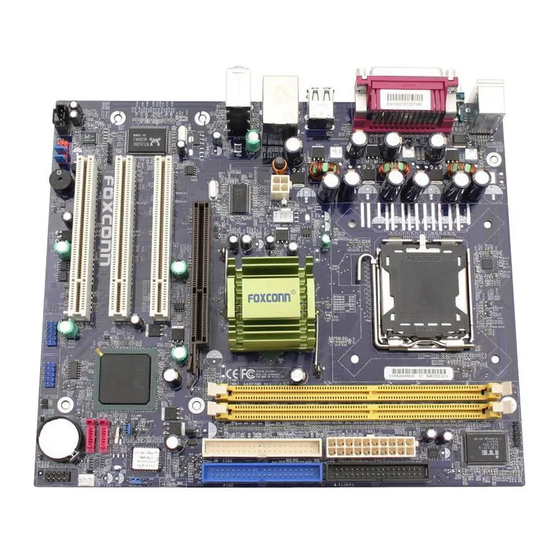
- Page 9 13. Front Panel Connector 19. PCI Slots 7. ATX Power Connector 14. SATA Connector 20. SPDIF Connector 21. F_Audio Connector 22. CD_IN Connector Note: The above motherboard layout is provided for reference only; please refer to the physical motherboard. 848P7MB Series User Manual...
- Page 10 Please refer to the motherboard layout prior to any installation and read the contents in this chapter carefully. This chapter includes the following information: Memory Power supply Rear Panel Connectors Other Connectors Expansion Slots Jumpers 848P7MB Series User Manual...
- Page 11 Installation Instructions ® This motherboard supports single Pentium 4 Processor including Prescott-T processor in an LGA775 package. It also supports Hyper-Threading Technology. Installation of CPU Load lever Load plate Load cap Load stiffener gLoa Lifted tab 848P7MB Series User Manual...
- Page 12 Chapter 2 Installation Instructions Correct Wrong 848P7MB Series User Manual...
- Page 13 Therefore, you should install CPU cooling fan and make sure that the cooling fan works normally at all times in order to prevent overheating and damaging to the CPU. Please refer to your CPU fan user guide to install it properly. 848P7MB Series User Manual...
- Page 14 3. The plastic clips at both sides of the DIMM slot will lock automatically. Warning : Be sure to unplug the AC power supply before adding or removing expansion cards or other system peripherals, especially the memory devices, otherwise your motherboard or the system memory might be seriously damaged. 848P7MB Series User Manual...
- Page 15 4-pin ATX_12V power connector Rear Panel Connectors This motherboard provides the ports as below: LAN Port Parallel Port (Printer Port) Line-in PS/2 Mouse Connector Line-out PS/2 Keyboard Microphone Connector Serial Port USB 2.0 Ports S/PDIF (COM1) Coaxial Out Port 848P7MB Series User Manual...
- Page 16 When using a two-channel sound source, the Line-out jack is used to connect to speaker or headphone; the Line-in port connects to an external CD player, tape player or other audio device. The Microphone jack is used to connect to the microphone. 848P7MB Series User Manual...
- Page 17 Ultra DMA 100/66 master device. Attention: Ribbon cables are directional, therefore, make sure to always con- nect with the cable on the same side as pin 1 of the IDE or FDD connector on the motherboard. 848P7MB Series User Manual...
- Page 18 IrDA Header: IR This connector supports wireless transmit- Empty ting and receiving device. Before using this function, configure the settings of IR Mode from the “Integrated Peripherals” section of the CMOS Setup. 848P7MB Series User Manual...
- Page 19 T X + ATA device to the motherboard. These con- nectors support the thin Serial ATA cables for primary internal storage devices. The current Serial ATA interface allows up to 150MB/s data SATA _1/SATA _2 transfer rate. 848P7MB Series User Manual...
- Page 20 To utilize this function, set “Case Open Warning” to “Enabled” in the “PC Health Status” section of the CMOS Setup. Save and exit, then boot the operating sys- tem once to make sure this function takes effect. 848P7MB Series User Manual...
- Page 21 3. Remove the bracket opposite the slot that you intend to use. 4. Align the card connector with the slot and press firmly until the card is completely seated on the slot. 5. Secure the card to the chassis with the screw you removed earlier. 848P7MB Series User Manual...
- Page 22 3 together with the jumper cap). 3. Turn the AC power supply back on. Warning: 1. Disconnect the power cable before adjusting the jumper settings. 2. Do not clear the CMOS while the system is turned on. 848P7MB Series User Manual...
- Page 23 BIOS is protected from being at- tacked by a serious virus, such as the CIH BIOS Lock virus. You will be unable to flash the BIOS to the Lock motherboard, when the system BIOS is protected. BIOS_WP Jumper 848P7MB Series User Manual...
-
Page 24: Standard Cmos Features
Appendix Chapter This chapter tells how to change system settings through the BIOS Setup menus. Detailed descriptions of the BIOS parameters are also provided. You have to run the Setup Program when the following cases occur: 1. An error message appears on the screen during the system POST process. - Page 25 Main Menu The items in the main menu are explained below: Standard CMOS Features The basic system configuration can be set up through this menu. BIOS Features The special features can be set up through this menu. 848P7MB Series User Manual...
- Page 26 Set Supervisor/User Password The supervisor/user password can be set up through this menu. Save & Exit Setup Save CMOS value settings to CMOS and exit setup. Exit Without Saving Abandon all CMOS value changes and exit setup. 848P7MB Series User Manual...
- Page 27 Access Mode to “CHS”, the related information should be entered manually. Enter the information directly from the keyboard and press < Enter>: Cylinder number of cylinders Head number of heads Precomp write pre-compensation Landing Zone landing zone Sector number of sectors 848P7MB Series User Manual...
- Page 28 The system boot will not stop for a diskette error; but it will stop for all other errors. All, But Disk/Key The system boot will not stop for a keyboard or disk error, but it will stop for all other errors. 848P7MB Series User Manual...
- Page 29 The BIOS POST will determine the amount of base (or conventional) memory installed in the system. Extended Memory The BIOS determines how much extended memory is present during the POST. Total Memory Total memory of the system. 848P7MB Series User Manual...
- Page 30 CPU clock range. If you want to know the detail information, please visit out website: http://www.foxconnchannel.com/ Warning: Be sure your selection is right. CPU overclock will be dangerous! We will not be responsible for any damage caused. 848P7MB Series User Manual...
- Page 31 Note: This function will not be displayed until a CPU that supports Hyper- Threading has been installed. Quick Power On Self Test (Default: Enabled) Enable this item to shorten the power on testing (POST) and have your system start up faster. 848P7MB Series User Manual...
- Page 32 This option is used to manage Prescott CPU thermal. Limit CPUID MaxVal (Default: Depend on CPU) The option is used to set limit CPUID MaxVal. Set Limit CPUID MaxVal to 3, should be "Disabled" for WinXP. 848P7MB Series User Manual...
- Page 33 DRAM Timing Selectable (Default: By SPD) This item determines DRAM clock/ timing using SPD or manual configuration. Init Display First (Default: Onboard/AGP) This item is used to set which display device will be used first when your PC starts up. 848P7MB Series User Manual...
- Page 34 Enhanced Mode, six HDDs at most will be supported (for those under Windows 2000 and Windows XP only); with it set to SATA Only, only the S-ATA HDD can be used. 848P7MB Series User Manual...
- Page 35 Onboard Device Menu AC97 Audio (Default: Auto) This option is used to set whether onboard AC97 Audio is enabled. Onboard LAN Control (Default: Enabled) This option is used to set whether the onboard LAN control is enabled. 848P7MB Series User Manual...
- Page 36 PWRON After PWR-Fail (Default: Off) This option is used to set what action the PC will take with the power supply when it resumes after a sudden power failure. 848P7MB Series User Manual...
- Page 37 If this item is enable, it allows the system to resume from a software power down or power saving mode whenever there is an incoming call to an installed fax/modem. This function needs to be supported by the relevant hardware and software. 848P7MB Series User Manual...
- Page 38 Date (of Month) Alarm This option is used to set the timing for the start-up date. Time (hh:mm:ss) Alarm This option is used to set the timing for the start-up time. 848P7MB Series User Manual...
- Page 39 ISA slot, this option does not apply. PCI/VGA Palette Snoop (Default: Disabled) If you use a nonstandard VGA card, use this option to solve graphic acceleration card or MPEG audio card problems (e.g., colors not accurately displayed). 848P7MB Series User Manual...
- Page 40 CPU is higher than setting value, the motherboard will send off warning information. Case Open Warning (Default: Disabled) This option is used to enable or disable case open warning function. The setting values are: Disabled and Enabled. 848P7MB Series User Manual...
- Page 41 This option is used to set the ratio of an unlocked CPU. Note: This option is invisible for locking frequency CPU. Warning: Be sure your selection is right. CPU overclock will be dangerous! We will not be responsible for any damage caused. 848P7MB Series User Manual...
- Page 42 Enter Password: Enter your password, not exceeding 8 characters, then press <Enter>. The password you enter will replace any previous password. When prompted, key in the new password and press <Enter>. 848P7MB Series User Manual...
-
Page 43: Save & Exit Setup
If you select this option and press <Enter>, the following message will appear in the center of the screen: Quit Without Saving (Y/N)?N Press <Y> to exit CMOS without saving your modifications; press <N> or <ESC> to return to the main menu. 848P7MB Series User Manual... -
Page 44: Utility Cd Content
Chapter The utility CD that came with the motherboard contains useful software and several utility drivers that enhance the motherboard features. This chapter includes the following information: Utility CD content Start to install drivers... - Page 45 If you want to know the detail information, please visit our website: http://www.foxconnchannel.com/ B. Adobe Reader C. Norton Internet Security 2004 3. Browse CD Click here to browse CD content. 4. Homepage Click here to visit FOXCONN motherboard homepage. 848P7MB Series User Manual...
- Page 46 Start to install drivers Select <Install Driver>, and click it to enter the install drivers screen. You can select the driver that you want to install and begin the setup steps. Follow screen order to install motherboard drivers 848P7MB Series User Manual...
Need help?
Do you have a question about the 848P7MB and is the answer not in the manual?
Questions and answers