Table of Contents
Advertisement
Statement:
This manual is the intellectual property of Foxconn, Inc. Although the
information in this manual may be changed or modified at any time,
Foxconn does not obligate itself to inform the user of these changes.
Trademark:
All trademarks are the property of their respective owners.
Version:
User's Manual V1.1 in English for 915G7MC/915P7MC/915GV7MC/
915GL7MC motherboard.
P/N: 91-181-U15-M7-1E
Symbol description:
Note: refers to important information that can help you to use motherboard
better.
Attention: indicates that it may damage hardware or cause data loss,
and tells you how to avoid such problems.
Warning: means that a potential risk of property damage or physical
injury exists.
More information:
If you want more information about our products, please visit Foxconn's
website:
http://www.foxconnchannel.com
Advertisement
Table of Contents

Related Manuals for Foxconn 915G7MC


Summary of Contents for Foxconn 915G7MC
- Page 1 This manual is the intellectual property of Foxconn, Inc. Although the information in this manual may be changed or modified at any time, Foxconn does not obligate itself to inform the user of these changes. Trademark: All trademarks are the property of their respective owners.
- Page 2 Item Checklist: Thanks for your purchasing Foxconn’s 915G7MC/915P7MC/915GV7MC/ 915GL7MC motherboard. Please check the package; if there are missing or dam- aged items, contact your distributor as soon as possible. 915G7MC/915P7MC/915GV7MC/915GL7MC motherboard (x1) Foxconn Utility CD (x1) 915G7MC/915P7MC/915GV7MC/915GL7MC User Manual (x1)
-
Page 3: Declaration Of Conformity
Declaration of conformity HON HAI PRECISION INDUSTRY COMPANY LTD 66 , CHUNG SHAN RD., TU-CHENG INDUSTRIAL DISTRICT, TAIPEI HSIEN, TAIWAN, R.O.C. declares that the product Motherboard 915G7MC/915P7MC/915GV7MC/915GL7MC is in conformity with (reference to the specification under which conformity is declared in accordance with 89/336 EEC-EMC Directive) EN 55022/A1: 2000 Limits and methods of measurements of radio disturbance... - Page 4 Declaration of conformity Trade Name: Foxconn 915G7MC/915P7MC/915GV7MC/915GL7MC Model Name: Industry Inc. Responsible Party: Address: 458 E. Lambert Rd. Fullerton, CA 92835 Telephone: 714-738-8868 Facsimile: 714-738-8838 Equipment Classification: FCC Class B Subassembly Type of Product: Motherboard Manufacturer: HON HAI PRECISION INDUSTRY...
-
Page 5: Table Of Contents
Table of Contents Chapter Product Introduction Chapter Installation Instructions Supply ..................... Chapter BIOS Description Standard CMOS Features ................25 BIOS Features ................... Advanced BIOS Features ................Advanced Chipset Features ..............Integrated Peripherals ................Power Management Setup ................. PnP/PCI Configurations ................PC Health Status .................. - Page 6 Warning: 1. Attach the CPU and heatsink using silica gel to ensure full contact. 2. It is suggested to select high-quality, certified fans in order to avoid damage to the motherboard and CPU due high temperatures. 3. Never turn on the machine if the CPU fan is not properly installed. 4.
- Page 7 This manual is suitable for motherboard of 915G7MC/ 915P7MC/915GV7MC/915GL7MC. Each motherboard is carefully designed for the PC user who wants diverse features. with onboard 100M LAN with onboard 1G LAN with 6-Channel audio with 8-Channel audio with 1394 function with SATA function with RAID function You can find PPID label on the motherboard.
- Page 8 Chapter Thank you for buying Foxconn’s 915 series motherboard. This series of motherboard is one of our new products, and offers superior performance, reliability and quality, at a reasonable ® price. This motherboard adopts the advanced Intel 915G/P/ GV/GL+ ICH6/ICH6R chipset, providing users a computer plat- form with a high integration-compatibility-performance price ratio.
- Page 9 Chapter 1 Product Introduction Main Features Size mATX form factor of 9.6 inch x 9.6 inch Microprocessor Supports Intel ® Prescott-T processor in an LGA775 package Supports FSB at 533 MHz/800 MHz Supports Hyper-Threading technology Supports FSB Dynamic Bus Inversion (DBI) Chipset 915G7MC series: Intel ®...
- Page 10 Chapter 1 Product Introduction Onboard Serial ATA (optional) 150 MBps transfer rate Supports four S-ATA devices Supports RAID 0, RAID 1, RAID 0+1, Matrix RAID (supported on ICH6R) Onboard 1394 (-E ) (optional) Support hot plug With rate of transmission at 400 Mbps Self-configured addressing Can connect with 2 independent 1394 units synchronously at most Onboard LAN (-L/-K) (optional)
- Page 11 Chapter 1 Product Introduction Expansion Slots Three PCI slots One PCI Express x16 Graphics slot (only for 915G/P) Advanced Features PCI 2.3 specification compliant Supports Windows 2000/XP soft-off Supports Wake-on-LAN function (optional) Supports PC Health function (capable of monitoring system voltage, CPU/ system temperature, and fan speed)
-
Page 12: Product Introduction
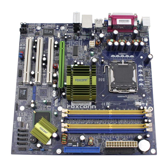
Chapter 1 Product Introduction Layout 1.4-pin ATX_12V Power Connector 15.Clear CMOS Jumper 2.PCI Express x16 Slot (optional) 16.Front Panel Connector 3.LGA775 CPU Socket 17.Serial ATA Connectors 4.North Bridge: 915G/P/GV/GL Chipset 18.FAN1 Connector 5.CPU Fan Connector 19.WOL Header (optional) 6.DIMM Slots (optional) 20.IrDA Header (optional) 7.South Bridge: ICH6/ICH6R Chipset 21.USB Headers... - Page 13 Chapter 1 Product Introduction Chapter This chapter introduces the hardware installation process, in- cluding the installation of the CPU, memory, power supply, slots, rear panel and pin headers, and the mounting of jumpers. Caution should be exercised during the installation of these modules.
- Page 14 Chapter 2 Installation Instructions ® This motherboard supports single Pentium 4 Processor including Prescott desktop CPUs in an LGA775 package. It also supports Hyper-Threading Technology and FSB Dynamic Bus Inversion (DBI). Installation of CPU Load lever Load plate Load cap Load stiffener gLoa Lifted tab...
- Page 15 Chapter 2 Installation Instructions Correct Wrong Lift up the lever. Use thumb to open the load plate. Be careful not to touch the contacts.
- Page 16 Chapter 2 Installation Instructions Note : Excessive temperatures will severely damage the CPU and system. Therefore, you should install CPU cooling fan and make sure that the cooling fan works normally at all times in order to prevent overheating and damaging to the CPU. Please refer to your CPU fan user guide to install it properly.
- Page 17 Chapter 2 Installation Instructions Memory This motherboard includes two or four 184-pin slots with 2.6 V for DDR. These slots support 256 Mb, 512 Mb and 1 Gb DDR technologies for x8 and x16 devices, and support maximum memory bandwidth of 3.2 GB/s in Single-Channel or Dual- Channel asymmetric mode, or 6.4 GB/s in Dual-Channel interleaved mode, as- suming DDR 333/400.
- Page 18 Chapter 2 Installation Instructions Power Supply This motherboard uses an ATX power supply. In order to avoid damaging any devices, make sure that they have been installed properly prior to connecting the power supply. 4-pin ATX_12 V Power Connector: PWR2 The ATX power supply connects to PWR2 and 4-pin ATX_12 V power connector provides power to the CPU.
-
Page 19: Installation Instructions
Chapter 2 Installation Instructions Rear Panel Connectors This motherboard provides the ports as below: For -6 models 1394 Port LAN Port Parallel Port (optional) (Printer Port) Line-in PS/2 Mouse Connector Line-out PS/2 Keyboard Microphone Connector Serial Port USB 2.0 Ports VGA Port (COM1) (only for 915 G/GV/GL) - Page 20 Chapter 2 Installation Instructions VGA Port (only for 915 G/GV/GL) The VGA Port is for output to a VGA-compatible device. 1394 Port (optional) This digital interface supports electronic devices such as digital cameras, scanners, and printers. USB 2.0 Ports These four Universal Serial Bus (USB) ports are available for connecting USB 2.0/1.1 devices.
- Page 21 Chapter 2 Installation Instructions Other Connectors This motherboard includes connectors for FDD devices, IDE HDD devices, Serial ATA devices, USB devices, IR module, and others. FDD connector: FLOPPY This motherboard includes a standard FDD connector, supporting 360 K, 720 K, 1.2 M, 1.44 M, and 2.88 M FDDs.
- Page 22 Chapter 2 Installation Instructions Front Panel Connector: FP1 This motherboard includes one connector for connect- P W R S W Empty P W R L E D ing the front panel switch and LED indicators. HD-LED R E S E T IDE LED Connector (HD-LED) The connector connects to the case’s IDE indicator LED indicating the activity status of hard disks.
- Page 23 Chapter 2 Installation Instructions Audio Connectors: CD_IN, AUX_IN (optional) CD_IN, AUX_IN is Sony standard CD audio connectors, it can be connected to a CD-ROM drive through a CD audio cable. CD_IN AUX_IN CD_L AUX_R CD_R AUX_L Speaker Connector: SPEAKER (optional) The speaker connector is used to connect speaker of the chassis.
- Page 24 Chapter 2 Installation Instructions S-ATA Connectors: SATA_1, SATA_2, SATA_3, SATA_4 The S-ATA header is used to connect the S-ATA device to the motherboard. These connectors support the thin GND GND Serial ATA cables for primary internal storage devices. T X + The current Serial ATA interface allows up to 150MB/s data transfer rate.
- Page 25 Chapter 2 Installation Instructions Addtional COM Header: COM2 This motherboard provides an additional serial COM header for your machine. SOUT DTR# Connect one side of a switching cable to the header, DSR# RTS# CTS# then attach the serial COM device to the other side of Empty the cable.
- Page 26 Chapter 2 Installation Instructions Expansion Slots This motherboard includes three 32-bit Master PCI bus slots and one PCI Ex- press x 16 slot (only for 915 G/P). PCI Slots The expansion cards can be installed in the three PCI slots. When you install or take out such cards, you must make sure that the power plug has been pulled out.
- Page 27 Chapter 2 Installation Instructions Jumpers The users can change the jumper settings on this motherboard if needed. This section explains how to use the various functions of this motherboard by chang- ing the jumper settings. Users should read the following content carefully prior to modifying any jumper settings.
- Page 28 Chapter 2 Installation Instructions BIOS TBL Jumper: JP2 The system cannot boot if the BIOS fails to be flashed in BIOS TBL conventional flash BIOS process. But not to worry when Enable you use the BIOS TBL function. It is used to protect BIOS “Top Boot Block”.
- Page 29 Chapter This chapter tells how to change system settings through the BIOS Setup menus. Detailed descriptions of the BIOS pa- rameters are also provided. You have to run the Setup Program when the following cases occur: 1. An error message appears on the screen during the system T-- This page is intentionally left blank --his POST process.
-
Page 30: Chapter Bios Description
Chapter 3 BIOS Description Enter BIOS Setup The BIOS is the communication bridge between hardware and software, correctly setting up the BIOS parameters is critical to maintain optimal system performance. Power on the computer, when the following message briefly appears at the bottom of the screen during the POST (Power On Self Test), press <Del>... - Page 31 Chapter 3 BIOS Description BIOS Features The special features can be set up through this menu. Advanced BIOS Features The advanced system features can be set up through this menu. Advanced Chipset Features The values for the chipset can be changed through this menu, and the sys- tem performance can be optimized.
-
Page 32: Standard Cmos Features
Chapter 3 BIOS Description Standard CMOS Features This sub-menu is used to set up the standard CMOS features, such as the date, time, HDD model and so on. Use the arrow keys select the item to set up, and then use the <PgUp> or <PgDn> keys to choose the setting values. Standard CMOS Features Menu Date This option allows you to set the desired date (usually as the current date) - Page 33 Chapter 3 BIOS Description Award (Phoenix) BIOS can support 3 HDD modes: CHS, LBA and Large or Auto mode. For HDD<528MB For HDD>528MB & supporting LBA (Logical Block Addressing) Large For HDD>528MB but not supporting LBA Auto Recommended mode Drive A/B This option allows you to select the kind of FDD to be installed, including “None”, [360K, 5.25 in], [1.2M, 5.25 in], [720K, 3.5 in], [1.44M, 3.5 in] and [2.88 M, 3.5 in].
- Page 34 Chapter 3 BIOS Description Memory This is a Display-Only Category, determined by POST (Power On Self Test) of the BIOS. Base Memory The BIOS POST will determine the amount of base (or conventional) memory installed in the system. Extended Memory The BIOS determines how much extended memory is present during the POST.
-
Page 35: Bios Features
Chapter 3 BIOS Description BIOS Features BIOS Features Menu [SuperBoot] SuperBoot (Default: Disabled) SuperBoot allows system-relevant information to be stored in CMOS upon the first normal startup of your PC, and the relevant parameters will be restored to help the system start up more quickly on each subsequent startup. The avail- able setting values are: Disabled and Enabled. - Page 36 Chapter 3 BIOS Description SuperSpeed Menu System Memory Frequency (Default: Auto) This option is used to set system memory frequency. CPU Clock Ratio (Default: Depend on CPU ) This option is used to set the ratio of an unlocked CPU. Auto Detect PCI Clk (Default: Enabled) This option is used to set whether the clock of an unused PCI slot will be disabled to reduce electromagnetic interference.
-
Page 37: Advanced Bios Features
Chapter 3 BIOS Description Advanced BIOS Features Advanced BIOS Features Menu CPU Feature Press <Enter> to set the items of CPU feature. Please refer to page 31. Hard Disk Boot Priority This option is used to select the priority for HDD startup. After pressing <Enter>, you can select the HDD using the <PageUp>/<PageDn>... - Page 38 Chapter 3 BIOS Description Boot Other Device (Default: Enabled) With this function set to Enabled, the system will boot from some other devices if the first/second/third boot devices failed. The available setting val- ues are: Disabled and Enabled. Security Option (Default: Setup) When it is set to “Setup”, a password is required to enter the CMOS Setup screen;...
-
Page 39: Advanced Chipset Features
Chapter 3 BIOS Description Advanced Chipset Features Advanced Chipset Features Menu DRAM Timing Selectable (Default: By SPD) This item determines DRAM clock/ timing using SPD or manual configuration. The available setting values are: By SPD and Manual. System BIOS Cacheable (Default: Enabled) Select “Enabled”... -
Page 40: Integrated Peripherals
Chapter 3 BIOS Description Integrated Peripherals Integrated Peripherals Menu Use the arrow keys to select your options; press the <Enter> key to enter the setup sub-menu. The options and setting methods are discussed below: Onchip IDE Menu SATA Mode (Default: IDE) (optional) This option is used to set the Serial ATA Mode. - Page 41 Chapter 3 BIOS Description PATA IDE Mode (Default: Primary) When On-Chip Serial ATA is set as “Combined Mode”, this option will be modified. It is used to set the PATA IDE Mode. The available setting values are: Primary, Secondary. SATA Port (Default: P2, P4 is Secondary) This option is used to set the Serial ATA Port.
- Page 42 Chapter 3 BIOS Description SuperIO Device Menu UART Mode Select (Default: IrDA) Use this option to select the UART mode. Setting values include Normal, IrDA, ASKIR. The setting value is determined by the infrared module installed on the board. UR2 Duplex Mode (Default: Half) This option is available when UART 2 mode is set to either ASKIR or IrDA.
-
Page 43: Power Management Setup
Chapter 3 BIOS Description Power Management Setup Power Management Setup Menu PCI Express PM Function (optional) Press <Enter> to set the item of PCI Express PM function. Please refer to page 37. ACPI Function (Default: Enabled) ACPI stands for “Advanced Configuration and Power Interface”. ACPI is a standard that defines power and configuration management interfaces be- tween an operating system and the BIOS. - Page 44 Chapter 3 BIOS Description Power Management Events Press <Enter> to set the items of power management events. Please refer to page 38. Primary IDE 0, Secondary IDE 0 (Default: Disabled) When these items are enabled, the system will restart the power saving time- out counters when any activity is detected on any of the drives or devices on the primary or secondary IDE channels.
- Page 45 Chapter 3 BIOS Description Power Management Events Menu Wake up by PCI card (Default: Enabled) This option is used to set the system to wake up by PCI card. The setting values are Disabled and Enabled. Wake up by Ring (Default: Enabled) If this item is enable, it allows the system to resume from a software power down or power saving mode whenever there is an incoming call to an installed fax/modem.
-
Page 46: Pnp/Pci Configurations
Chapter 3 BIOS Description PnP/PCI Configurations PnP/PCI Configurations Menu Reset Configuration Data (Default: Disabled) This option is used to set whether the system is permitted to automatically distribute IRQ DMA and I/O addresses when each time the machine is turned on. -
Page 47: Pc Health Status
Chapter 3 BIOS Description PC Health Status PC Health Status menu Shutdown Temperature (Default: Disabled) This option is used to set the system temperature upper limit. When the temperature exceeds the setting value, the motherboard will automatically cut off power to the computer. The setting values are Disabled and 60 C/140 C/149 F, 70... -
Page 48: Load Fail-Safe Defaults
Chapter 3 BIOS Description Load Fail-Safe Defaults Press <Enter> to select this option. A dialogue box will pop up that allows you to load the default BIOS settings. Select <Y> and then press <Enter> to load the defaults. Select <N> and press <Enter> to exit without loading. The defaults set by BIOS set the basic system functions in order to ensure system stability. -
Page 49: Save & Exit Setup
Chapter 3 BIOS Description If you do not want to set a password, just press <Enter> when prompted to enter a password, and in the screen the following message will appear. If no password is keyed in, any user can enter the system and view/modify the CMOS settings. PASSWORD DISABLED!!! Press any key to continue …... - Page 50 Chapter The utility CD that came with the motherboard contains use- ful software and several utility drivers that enhance the motherboard features. This chapter includes the following information: Utility CD content Start to Install drivers...
-
Page 51: Chapter Driver Cd Introduction
SuperUpdate function can help to update the BIOS through Internet directly. B. Adobe Reader C. Norton Internet Security D. Word Perfect Office 12 3. Browse CD Click here to browse CD content. 4. HomePage Click here to visit Foxconn motherboard homepage. -
Page 52: Start To Install Drivers
Chapter 4 Driver CD Introduction Note: 1. Install the latest patch first if your OS is Windows XP or Win- dows 2000. 2. Follow the CD screen order to install your motherboard drivers. Start to Install Drivers Click <Install Driver> to enter the driver installation menu (as shown in Figure 1). -
Page 53: Appendix Using 8-Channel Audio (Optional)
Appendix Using 8-channel Audio (optional) 1. Introduction 8-channel audio is the highest surround sound standard available adding two speakers over existing 6-channel (5.1) audio set-ups. 8-channel surround sound is already a standard feature for premium consumer audio devices, so it only makes sense that as users increasingly use their PCs to listen to the latest multimedia content that 8-channel support makes the migration as a standard PC feature. - Page 54 Appendix Blue Black Green Orange Grey STEP 2. You need to install the driver for the audio chip before you can use the 8-channel audio function. Click here...
- Page 55 Appendix STEP 3. After installation of the audio driver, you’ll find an icon on the taskbar’s status area. Double click the icon, you will see the following picture. STEP 4. Click “Speaker configuration”. The following picture will appear. STEP 5. Make sure you select “8CH Speaker” from the above picture. Now you can enjoy the 8-channel audio function.
Need help?
Do you have a question about the 915G7MC and is the answer not in the manual?
Questions and answers