Table of Contents
Advertisement
Statement:
This manual is the intellectual property of FOXCONN, Inc. Although the
information in this manual may be changed or modified at any time,
FOXCONN does not obligate itself to inform the user of these changes.
Trademark:
All trademarks are the property of their respective owners.
Version:
User Manual V1.0 in English for 761GXK8MC series motherboard.
P/N: 91-181761GM0E-00
Symbol description:
Note: refers to important information that can help you to use motherboard
better.
Attention: indicates that it may damage hardware or cause data loss,
and tells you how to avoid such problems.
Warning: means that a potential risk of property damage or physical
injury exists.
More information:
If you want more information about our products, please visit FOXCONN
website:
http://www.foxconnchannel.com
Advertisement
Table of Contents

Related Manuals for Foxconn 761GXK8MC


Summary of Contents for Foxconn 761GXK8MC
- Page 1 This manual is the intellectual property of FOXCONN, Inc. Although the information in this manual may be changed or modified at any time, FOXCONN does not obligate itself to inform the user of these changes. Trademark: All trademarks are the property of their respective owners.
-
Page 2: Declaration Of Conformity
HON HAI PRECISION INDUSTRY COMPANY LTD 66 , CHUNG SHAN RD., TU-CHENG INDUSTRIAL DISTRICT, TAIPEI HSIEN, TAIWAN, R.O.C. declares that the product Motherboard 761GXK8MC is in conformity with (reference to the specification under which conformity is declared in accordance with 89/336 EEC-EMC Directive) þ... - Page 3 Declaration of conformity Trade Name: W inFast Model Name: 761GXK8MC Responsible Party: PCE Industry Inc. Address: 458 E. Lambert Rd. Fullerton, CA 92835 Telephone: 714-738-8868 Facsimile: 714-738-8838 Equipment Classification: FCC Class B Subassembly Type of Product: Motherboard Manufacturer: HON HAI PRECISION INDUSTRY...
-
Page 4: Table Of Contents
Table of Contents Product Introduction Chapter Main Features .................... 2 Motherboard Layout ................... 4 Rear Panel Connectors ................5 Installation Instructions Chapter CPU ......................8 Memory ....................12 Power Supply ..................13 Other Connectors ..................14 Expansion Slots ..................19 Jumpers .................... - Page 5 Table of Contents Chapter Directions for Bundled Software SuperStep ....................56 SuperUpdate .................... 59 SuperLogo ....................64 Chapter Special BIOS Functions SuperBoot ....................67 SuperBIOS-Protect ................... 68 SuperSpeed ..................... 69 SuperRecovery ..................70...
- Page 6 Warning: 1. Attach the CPU and heatsink using silica gel to ensure full contact. 2. It is suggested to select high-quality, certified fans in order to avoid damage to the motherboard and CPU due to high temperature. 3. Never turn on the machine if the CPU fan is not properly installed. 4.
- Page 7 This manual is suitable for motherboard of 761GXK8MC series. Each motherboard is carefully designed for the PC user who wants diverse features. with onboard 10/100M LAN with onboard Gigabit LAN with 6-channel audio with 8-channel audio with 1394 with SATA with RAID You can find PPID label on the motherboard.
- Page 8 Chapter T hank you f or b uyin g W in Fast 7 61 GX K8 MC series motherboard. This series of motherboard is one of our new products, and offers superior performance, reliability and quality, at a reasonable price. This motherboard adopts the advanced SiS761GX+SiS964 chipset, providing users a computer platform with a high integration-compatibility-per- formance price ratio.
-
Page 9: Chapter 1 Product Introduction
Chapter 1 Product Introduction Main Features Size mATX form factor of 9.6” x 9.1” Microprocessor Supports Socket 754 for AMD Sempron / Athlon 64 Processor Supports HyperTransport Technology up to 1600MT/s bandwidth Chipset SiS Chipset: SiS 761GX (North Bridge) +SiS 964 (South Bridge) System Memory Two 184-pin DDR DIMM slots Supports PC3200/2700/2100 memory... - Page 10 Chapter 1 Product Introduction Onboard LAN (-L) Supports10/100 Mbps Ethernet LAN interface built-in on board Note: The shielded LAN cable are recommended. Onboard Audio(-6) AC’ 97 2.3 Specification Compliant Onboard Line-in jack, Microphone jack, Line-out jack Supports 6-channel audio(setting via software) BIOS Licensed advanced AWARD (Phoenix) BIOS, supports flash ROM, Plug-and- Play...
-
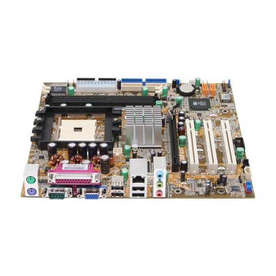
Page 11: Motherboard Layout
Chapter 1 Product Introduction Motherboard Layout 16 17 18 13 14 15 15. SATA Connectors 1. S/PDIF_OUT Connector 16. Speaker Connector 2. F_Audio Connector 17. System Fan1 Connector 3. AUX_IN Connector(optional) 18. Clear CMOS Jumper 4. CD_IN Connector 19. IDE Connectors 5. -
Page 12: Rear Panel Connectors
Chapter 1 Product Introduction Rear Panel Connectors This motherboard provides the following ports as below: 1394 Port Parallel Port LAN Port (optional) (Printer Port) Line-in PS/2 Mouse Port Line-out Microphone PS/2 Keyboard Port Serial Port VGA Connector USB 2.0 Ports (COM1) Line in, Line out, Microphone W hen using a 2-channel sound source, the Line out jack is used to connect to... - Page 13 Chapter 1 Product Introduction Chapter This chapter introduces the hardware installation process, including the installation of the CPU and memory. It also addresses the connection of your power supply,connection of hard drive and floppy drive data cables, and setting up various other feature of the motherboard.
-
Page 14: Chapter 2
Chapter 2 Installation Instructions Notes: Take note of the following precautions before you install components or change settings. 1. Use a grounded wrist strap or touch a safely grounded object, such as an attached power supply, before handling components to avoid damaging them due to static electricity. -
Page 15: Cpu
Chapter 2 Installation Instructions This motherboard Supports Socket 754 for AMD Sempron / Athlon 64 Pro- cessor with a 1600 MT/s bandwidth and HyperThansport Technology. Attention: The CPU pins must be properly aligned with the holes in the socket, otherwise the CPU may be damaged. Installation of CPU Follow these steps to install the CPU. - Page 16 Chapter 2 Installation Instructions Installation of CPU Fan New technology allows processors to run at higher and higher frequencies. To avoid p rob lems arisin g f r om hig h -sp eed op erat io n , f o r exam p le, overheating, you need to install the proper fan.
- Page 17 Chapter 2 Installation Instructions 3. Place the cooling set onto the re 4. Align the other end of the reten tention mechanism. Attach one tion bracket to fasten the cooling end of the retention bracket to re set on the top of the retention tention mechanism.
- Page 18 Chapter 2 Installation Instructions Note: Excessive temperatures will severely damage the CPU and system. Therefore, you should install CPU cooling fan and make sure that the cooling fan works normally at times in order to prevent over- heating and damaging to the CPU. For the latest CPU support list, please visit the website: http://www.foxconnchannel.com...
-
Page 19: Memory
Chapter 2 Installation Instructions Memory This motherboard includes two 184-pin slots with 266/333/400 MHz Single Chan- nel DDR DRAM interface, You must install at least one memory module to en- sure normal operation. If you install two modules, they must be the same speed. Mixing memory modules from different manufactures are not recommended. -
Page 20: Power Supply
Chapter 2 Installation Instructions Power Supply This motherboard uses an ATX power supply. In order to avoid damaging any devices, make sure that they have been installed properly prior to connecting the power supply. +5V_AUX GN D PWROK +1 2V +3. -
Page 21: Other Connectors
Chapter 2 Installation Instructions Other Connectors This motherboard includes connectors for FDD devices, IDE HDD devices, SATA devices, USB devices, 1394 devices, IR module, CPU fan, system fan, and others. FLOPPY This motherboard includes a standard FLOPPY interface, supporting 360 K, 720 K, 1.2 M, 1.44 M, and 2.88 M FDDs. - Page 22 Chapter 2 Installation Instructions Front Panel Connector: FP1 This motherboard includes one connector for PW R-LED HDD-LED connecting the front panel switch and LED RESET-SW PWR-SW indicator. Hard Disk LED Connector (HDD-LED) FPFP1! The connector connects to the case’s IDE indicator LED indicating the activity status of hard disks.
- Page 23 Chapter 2 Installation Instructions USB Header: F_USB 1, F_USB 2 Besides four USB ports on the rear panel, the series of motherboards also have two 10-pin headers on board which may connect to front panel USB cable (optional) to provide additional four USB ports. Empty Empty F_USB 1...
- Page 24 Chapter 2 Installation Instructions 1394 Connectors: F_1394_1,F_1394_2 Empty (Optional) TPB - TPB + The 1394 expansion cable can be connected to either the front (provided that the front panel TPA - TPA + of your chassis is equipped with the appropri- ate interface) or real panel of the chassis.
- Page 25 Chapter 2 Installation Instructions Speaker Connector: SPKEAKER Emypty The speaker connector is used to connect speaker of the chassis. SPKJ SPEAKER RTS# Additional COM Connector: COM2 DCD# This board provides an additional serial COM connector for your computer. You need connect the switching-cable to this connector first, and then connect the serial DSR# EMPTY...
-
Page 26: Expansion Slots
Chapter 2 Installation Instructions Expansion Slots This motherboard includes three 32-bit Master PCI bus slots and one PCI Ex- press x16 slot. PCI Slots The expansion cards can be installed in the three PCI slots. W hen you install or take out such cards, you must make sure that the power plug has been pulled out. -
Page 27: Installing An Expansion Card
Chapter 2 Installation Instructions Installing an expansion card 1. Before installing the expansion card, read the documentation that came with it and make the necessary hardware settings for the card. 2. Make sure to unplug the power cord before adding or removing expansion cards. -
Page 28: Jumpers
Chapter 2 Installation Instructions Jumpers Users can change the jumper settings on this motherboard if needed. This section explains how to use the various functions of this motherboard by chang- ing the jumper settings. Users should read the following contents carefully prior to modifying any jumper settings. - Page 29 Chapter 2 Installation Instructions BIOS-Protection Jumper: J5 Write Disable 1 2 3 The motherboard BIOS is inside the FW H. If the jumper FW H_EN is set as disabled (Pin2 & Pin3), the system BIOS is protected from being Write Enable(default) 1 2 3 attacked by a serious virus, such as the CIH virus.
-
Page 30: Chapter 3
Chapter 2 Installation Instructions Starting up for the first time 1. After making all the connections, replace the system case cover. 2. Make sure that all switches are turned off. 3. Turn on the devices in the following order. Monitor External SCSI devices (starting with the last device on the chain) System power 4. - Page 31 Chapter This chapter tells how to change system settings through the BIOS Setup menus. Detailed descriptions of the BIOS param- eters are also provided. You have to run the Setup Program when the following cases occur: T-- This page is intentionally left blank --his 1.
-
Page 32: Chapter 3 Bios Description
Chapter 3 BIOS Description Enter BIOS Setup The BIOS is the communication bridge between hardware and software, correctly setting up the BIOS parameters is critical to maintain optimal system performance. Power on the computer, when the following message briefly appears at the bottom of the screen during the POST (Power On Self Test), press <Del>... - Page 33 Chapter 3 BIOS Description Advanced BIOS Features The advanced system features can be set up through this menu. Advanced Chipset Features The values for the chipset can be changed through this menu, and the sys- tem performance can be optimized. Integrated Peripherals All onboard peripherals can be set up through this menu.
-
Page 34: Standard Cmos Features
Chapter 3 BIOS Description Standard CMOS Features This sub-menu is used to set up the standard CMOS features, such as the date, time, HDD model and so on. Use the arrow keys select the item to set up, and then use the <PgUp> or <PgDn> keys to choose the setting values. Standard CMOS Features Menu Date This option allows you to set the desired date (usually as the current date) - Page 35 Chapter 3 BIOS Description Award (Phoenix) BIOS can support 4 HDD modes: CHS, LBA and Large or Auto mode. For HDD<528MB For HDD>528MB & supporting LBA (Logical Block Addressing) Large For HDD>528MB but not supporting LBA Auto Recommended mode Drive A/B This option allows you to select the kind of FDD to be installed, including “None”, [360K, 5.25in], [1.2M, 5.25in], [720K, 3.5in], [1.44M, 3.5in] and [2.88 M, 3.5in].
- Page 36 Chapter 3 BIOS Description Memory This is a Displays-Only Category, detemined by POST(Power On Self Test) of the BIOS. Base Memory The BIOS POST will detemine the amount of base (or conventional) memory installed in the system. Extended Memory The BIOS determines how much extended memory is present during the POST.
-
Page 37: Bios Features
Chapter 3 BIOS Description BIOS Features BIOS Features Menu v[SuperBoot] SuperBoot SuperBoot allows system-relevant information to be stored in CMOS upon the first normal startup of your PC, and the relevant parameters will be restored to help the system start up more quickly on each subsequent startup. v[SuperBIOS-Protect] SuperBIOS-Protect Super-BIOS Protect funtion protects your PC from being affected by viruses, e.g. -
Page 38: Advanced Bios Features
Chapter 3 BIOS Description Advanced BIOS Features Advanced BIOS Features Menu vHard Disk Boot Priority This option is used to select the priority for HDD startup. After pressing <Enter>, you can select the HDD using the <PageUp>/<PageDn> or Up/ Down arrow keys, and change the HDD priority using <+> or <->; you can exit this menu by pressing <Esc>. - Page 39 Chapter 3 BIOS Description vSwap Floppy Drive If you have two floppy diskette drives in your system, this item allows you to swap the assigned drive letters. vBoot Up Floppy Seek This option controls whether the BIOS checks for a floppy drive while booting up.
- Page 40 Chapter 3 BIOS Description vOS Select For DRAM > 64MB This item is only required if you have installed more than 64 MB of memory and you are running the OS/2 operating system. Otherwise, leave this item at the default. vHDD S.M.A.R.T Capability This option is used to enable or disable hard disk’s S.M.A.R.T.(Self-Monitoring, Analysis,and Reporting Technology) support function.
-
Page 41: Advanced Chipset Features
Chapter 3 BIOS Description Advanced Chipset Features Advanced Chipset Features Menu vDRAMConfiguration Press enter to set the items about DRAM Configuration. vHyperTransport Control Press enter to set the items about HyperTransport Control. vOnChip VGA Control Press enter to set the items about OnChip VGA Control. vSystem BIOS Cacheable Select “Enabled”... - Page 42 Chapter 3 BIOS Description DRAM Configuration Menu vTime Mode This item is used to set time mode. vMemclock index value<Mhz> This item is used to set memclock value. vCAS# Latency <Tc1> This option controls the CAS latency, which determines the timing delay (in clock cycles) before SDRAM starts a read command after receiving it.
- Page 43 Chapter 3 BIOS Description vRow to Row delay <Trp> W hen DRAM is refreshed, both rows and columns are addressed separately. This setup item allows you to determine the timing of the transition from RAS (row address strobe) to CAS (column addres strobe). The less the clock cycles, the faster the DRAM performance.
- Page 44 Chapter 3 BIOS Description HyperTransport Control Memu HT-Width The available setting values are:8 bits,16 bits and Auto. vHT-Speed The available setting values are:200MHz,400MHz,600Mhz and 800MHz.
- Page 45 Chapter 3 BIOS Description Onchip VGA Control Memu vVGA Share Memory Size This option selects the size of on-chip frame buffer for vga output. vAGP Aperture Size The option defines the size of the aperture if you use an AGP graphic adapter. The aperture is a portion of the PCI memory address range dedicated for graphic memory address space.
-
Page 46: Integrated Peripherals
Chapter 3 BIOS Description Integrated Peripherals Integrated Peripherals Menu vSIS OnChip IDE Device Press enter to set onchip IDE device. vSIS OnChip PCI Device Press enter to set onchip PCI device. vOnboard SuperIO Device Press enter to set onchip onboard SuperIO device. vIDE HDD Block Mode This item is used to set whether the IDE HDD Block Mode is allowed. - Page 47 Chapter 3 BIOS Description SIS Onchip IDE Device Menu vInternal PCI/IDE This option is used to set the ports of onboard IDE. vIDE Primary/Secondary Master/Slave PIO These four items let you assign which kind of PIO(Programmer Input/Output) is used by IDE devices. Choose “Auto” to let the system auto detect which PIO mode is the best or select a PIO mode from 0-4.
- Page 48 Chapter 3 BIOS Description SIS OnChip PCI Device Menu vSIS USB Controller This option is used to enable or disable SIS USB controller. vUSB 2.0 Supports This option is used to enable or disable USB 2.0. vUSB Keyboard Support This option is used to set USB keyboard support. vUSB Mouse Support This option is used to set USB mouse support.
- Page 49 Chapter 3 BIOS Description Onboard SuperIO Device Menu vOnboad FDC Controller This option is used to set whether the onboard FDC controller is enabled. vOnboard Serial Port 1/2 These options are used to assign the I/O address and interrupt request (IRQ) for the onboard serial port 1/2.
-
Page 50: Power Management Setup
Chapter 3 BIOS Description Power Management Setup Power Management Setup Menu vACPI function ACPI stands for “Advanced Configuration and Power Interface”. ACPI is a standard that defines power and configuration management interfaces be- tween an operating system and the BIOS. In other words, it is a standard that describes how computer components work together to manage system hardware. - Page 51 Chapter 3 BIOS Description vMODEM Use IRQ This option is used to set the IRQ in which the modem can use. The system will automatically wake up when the modem receives an incoming call. vHot Key Function As This option is used to set the hot key function. vHDD Off After This option is used to set the time of HDD off.
- Page 52 Chapter 3 BIOS Description PM W ake up Events menu vIRQ [3-7,9-15],NMI This option is used to enable or disable IPQ[3-7,9-15,NMI. vIRQ 8 Break Suspend This option is used to enalbe or disable IRQ 8 break suspend. vRING Power Up Control If this option is enabled,it allows the system to resume from a software power down or power saving mode whenever there is an incoming call to an install- ed fax/modem.This function needs to be supported by the relevant hardware...
- Page 53 Chapter 3 BIOS Description vPower Up by Alarm This option used to set the time of the start-up function. In order to use this function, the start-up password function must be cancelled and the PC power source must not be turned off. vMonth Alarm This option is used to set the timing for the start-up month.
-
Page 54: Pnp/Pci Configurations
Chapter 3 BIOS Description PnP/PCI Configurations PnP/PCI Configurations Menu vInit Display First This item is used to set which display device will be used first when your PC starts up. vReset Configuration Data This option is used to set whether the system is permitted to automatically distribute IRQ DMA and I/O addresses when each time the machine is turned vResources Controlled By This option is used to define the system resource control scheme. -
Page 55: Pc Health Status
Chapter 3 BIOS Description PC Health Status PC Health Status Menu vCase Opened Waring These option is used to enable or disable case open warning function. vCPU Vcore,+3.3V/+5V/+12V,CPU Temp,Systerm Temperature,CPU FAN Speed,Systerm FAN Speed These items display the current status of all of the monitored hardware device/components such as CPU voltage, temperatures and all fan’s speeds. -
Page 56: Frequency/Voltage Control
Chapter 3 BIOS Description Frequency/Voltage Control Frequency/Voltage Control Menu Auto Detect PCI Clk This option is used to set whether the clock of an unused PCI slot will be disabled to reduce electromagnetic interference. Async PCI clock This option is used to enable or disable Async PCI clock. vSpread Spectrum If you enable spread spectrum, it can significantly reduce the EMI (ElectroMagne -tic Interference) generated by the system. -
Page 57: Load Fail-Safe Defaults
Chapter 3 BIOS Description Load Fail-Safe Defaults Select this option to press <Enter>, it will pop out a dialogue box to allow you to load default set by BIOS. Select <Y> and then press Enter to load default. Select <N> and press <Enter>, it will not load. The defaults set by BIOS have set the basic functions of system in order to ensure the stability of system. -
Page 58: Save & Exit Setup
Chapter 3 BIOS Description Under the menu “Advanced BIOS Features Setup”, if you select “System” in Security Option, the screen will prompt you to enter password once the system is started or you want to enter CMOS setting program. If the password is wrong, it will refuse you to continue. - Page 59 Chapter The utility CD that comes with the motherboard contains useful software and several utility drivers that enhance the mother- board features. This chapter includes the following information: Utility CD content Start to install drivers...
-
Page 60: Driver Cd Introduction
SuperUpdate function can help to update the BIOS through Internet. B. Adobe Reader C. Norton Internet Security D. Word Perfect Office 12 (Optional) 3. Manual Click to browse the manual. 3. Browse CD Click to browse this CD. 4. Homepage Click here to visit FOXCONN motherboard homepage. -
Page 61: Start To Install Drivers
Chapter 4 Driver CD Introduction Start to install drivers Select <Install Driver> to enter the driver installation menu (as following picture). Click the relevant button to install the Drivers. Click here... - Page 62 Chapter 4 Driver CD Introduction Chapter This chapter will introduce how to use attached software. This chapter includes the following information: SuperStep SuperUpdate SuperLogo...
-
Page 63: Chapter 5 Directions For Bundled Software
Adjust System Fan1 warning Minimize Window criteria Exit Program About SuperStep Adjust CPU Fan warning SuperStep Help criteria Link to FOXCONN Website Adjust System Fan2 Go to Fan warning criteria page Apply the Reset the adjust- warning criteria ments to default... - Page 64 Chapter 5 Directions for Bundled Software Adjust voltages warning criteria (upper limit) Current voltage readings Go to Voltage page Reset the warning Apply the Adjust voltages criteria to default adjustments warning criteria settings (Lower limit) Current CPU Adjust CPU tem- Temperature perature warning criteria...
- Page 65 Chapter 5 Directions for Bundled Software Current PCI Current CPU Express clock Clock Current PCI clock Current CPU Adjust the CPU Ratio External Frequency Reset to the default Go to Apply the settings Clock page adjustments Check for the system to auto- matically provide warning mes- sages...
-
Page 66: Superupdate
Minimize Window Current Exit Program BIOS Information BIOS Update Setting About SuperUpdate SuperUpdate Help Link to Foxconn Website Connect to server Backup system and popup a list of BIOS to an image available BIOSs for file users to download... - Page 67 Chapter 5 Directions for Bundled Software Backup BIOS to local image: 1. Click <Backup> and name your BIOS binary file to backup current BIOS. 2. Click <OK> to finish the backup process. Update BIOS from local image: 1. Click <Load> to load the BIOS file.
- Page 68 Chapter 5 Directions for Bundled Software 2. Click <Update>, the following message will appear. 3. Click <Yes> to backup the current BIOS, then the following picture will appear. 4. Click <OK >, then click <Update>.
- Page 69 Chapter 5 Directions for Bundled Software 5. Now is updating. 6. Click <Restart>.
- Page 70 Chapter 5 Directions for Bundled Software Update BIOS: 1. Click <Latest BIOS> to automatically update the BIOS from the server. 2. The following procedure is the same as Update BIOS from local image.
-
Page 71: Superlogo
The best resolution is 136 x 84 for top-right logo and 640 x 480 or 800 x 600 for full screen logo. Using SuperLogo: Display the Flash Information Minimize Window BIOS Write Exit Program Protect Status About SuperLogo BIOS Flash SuperLogo Help Rom Free Space Link to Foxconn website Go to ROM Info. page... - Page 72 Chapter 5 Directions for Bundled Software Full screen mode Top-Right mode Follow the Boot without logo Wizard to complete the logo update Go to Change Logo page Backup whole Backup Logo BIOS image Follow the Wizard to complete the backup function Go to Backup page Browse a BIN file BIOS image...
- Page 73 Chapter 5 Directions for Bundled Software Chapter This chapter will introduce new functions of BIOS and how to use them in detail. It can further exert the max potential of motherboard to bring you super-value enjoyment. This chapter introduces the following new functions of BIOS: SuperBoot SuperBIOS-Protect SuperSpeed...
-
Page 74: Chapter 6 Special Bios Functions
Chapter 6 Special BIOS Functions SuperBoot SuperBoot technology greatly reduces the long boot process time of computers. A BIOS without SuperBoot has to perform many routines every time when the system starts, such as checking the system core and initializing system peripherals. -
Page 75: Superbios-Protect
Chapter 6 Special BIOS Functions SuperBIOS-Protect The BIOS of the motherboard is contained inside the Flash ROM. Severe vi- ruses such as CIH virus are so dangerous that it may overwrite the BIOS of the motherboard. If the BIOS has been damaged, the system will be unable to boot. W e provide the following solution which protects the system BIOS from being attacked by such viruses. -
Page 76: Superspeed
Chapter 6 Special BIOS Functions SuperSpeed SuperSpeed is a powerful and efficient Easy Technology for PC DIY fans. It offers a friendly interface. The users can also realize in the BIOS setup the CPU core voltage adjustability. Procedures: Correctly install your CPU. Plug in other configurations and restore the system. -
Page 77: Superrecovery
Chapter 6 Special BIOS Functions SuperRecovery SuperRecovery is an easy-to-operate tool for backing up or recovering your hard disk data. It offers simplified user interfaces with hotkey access and allows you to experience unprecedented high security and reliability with extra functions, such as hotkey launch, and powerful anti-virus protection. - Page 78 Chapter 6 Special BIOS Functions Hard Disk Selection: The hard disk selection menu will be displayed after you press the hotkey, listing all the IDE HDDs installed in your system. You can switch the highlight bar to make a selection and press “Enter” to confirm it. Attention: 1) Make sure that you have selected a HDD before entering the main menu.
-
Page 79: Main Menu
Chapter 6 Special BIOS Functions Main Menu: Select a HDD to enter main menu. There are five function items, “DIVIDE HID- DEN PARTITION”, “RELEASE HIDDEN PARTITION”, “BACKUP”, “RECOVERY” and “CHANGE PASSWORD”. You can switch the highlight bar to make a selec- tion on the operation which should be performed on the HDD and confirm your selection by pressing <Enter>. - Page 80 Chapter 6 Special BIOS Functions Attention : 1) All the data will be cleared after division is in process. So you’d better do the division against an empty HDD. 2) At the same time, the HDD capacity will decrease to make space for the hidden partition, which is unavailable for your normal use.
- Page 81 Chapter 6 Special BIOS Functions Backup: Select BACKUP to enter the Backup interface, where you can find the following three sub-function items: “BACKUP CMOS SETUP”, “BACKUP PARTITION TABLE” and “BACKUP HARDDISK DATA”. Switch the highlight bar by pressing the arrow keys to make a selection and then press “Enter”...
- Page 82 Chapter 6 Special BIOS Functions 3. Backup Harddisk Data: 1) If there are active partitions (system partition), you can choose an active partition or the whole disk for backing up. But only one can be taken between the two choices. Old data will be replaced by the newly backed 2) Backing up with the progress bar showing.
- Page 83 Chapter 6 Special BIOS Functions 3) A report with all the critical data on this operation will be listed after backing up is completed. Original Size: The data size loaded in selected partition. Valid Size: The size of valid data. Elapsed Time: How long the process took to complete.
- Page 84 Chapter 6 Special BIOS Functions 1. Recover CMOS Setup: This function can help to restore the latest backup of CMOS settings you made. 2. Recover Partition Table: This function can help to recover all partition tables including extended partitions.
- Page 85 Chapter 6 Special BIOS Functions 3. Recover Hard disk Data: This option is used to restore the backed up data from the hidden partition. 4. Back to Main: This option is used to quit the Recovery interface. CHANGE PASSWORD Introduction: Select CHANGE PASSW ORD to enter the Change Password interface.
Need help?
Do you have a question about the 761GXK8MC and is the answer not in the manual?
Questions and answers