Table of Contents
Advertisement
Quick Links
Statement:
This manual is the intellectual property of Foxconn, Inc. Although the information
in this manual may be changed or modified at any time, Foxconn does not
obligate itself to inform the user of these changes. Additionally, Foxconn does
not accept responsibility for any direct or indirect accident relating with the use
of this manual.
Trademark:
All trademarks are the property of their respective owners.
Intel
and Pentium
®
PS/2 and OS/2 are the registered trademarks of IBM, Inc.
Windows
95/98/2000/NT/XP/Me is the registered trademark of Microsoft.
®
Award
is the registered trademark of Award, Inc.
®
Version:
User manual V1.0 in English for 875A02 series
P/N:91-181-U75-10-00
Symbol description:
Note:
refers to important information that can help you use motherboard better.
Attention:
indicates that it may damage hardware or cause data loss, and tells
you how to avoid such problems.
Warning:
means that a potential risk of property damage or physical injury exists.
More information:
If you want more information about our products, please visit Foxconn's
website:
Foxconn: www.foxconnchannel.com
875A02-English preface-V1.0-010604.p65
are registered trademarks of Intel Corporation.
®
1
2004-4-12, 13:39
Advertisement
Table of Contents

Related Manuals for Foxconn 875A02


Summary of Contents for Foxconn 875A02
- Page 1 Statement: This manual is the intellectual property of Foxconn, Inc. Although the information in this manual may be changed or modified at any time, Foxconn does not obligate itself to inform the user of these changes. Additionally, Foxconn does not accept responsibility for any direct or indirect accident relating with the use of this manual.
- Page 2 Item Checklist: Thanks for your purchasing Foxconn’s 875A02 series motherboard. Please check the package; if there are missing or damaged items, contact your distributor as soon as possible. 875A02 series motherboard (x1) Foxconn Utility CD (x1) User manual (x1) SATA RAID user manual (x1)
-
Page 3: Declaration Of Conformity
66 , CHUNG SHAN RD., TU-CHENG INDUSTRIAL DISTRICT, TAIPEI HSIEN, TAIWAN, R.O.C. declares that the product Mainboard 875A02 series is in conformity with (reference to the specification under which conformity is declared in accordance with 89/336 EEC-EMC Directive) EN 55022/A1: 2000... - Page 4 : (1) this device may not cause harmful interference, and (2) this device must accept any interference received, including interfer- ence that may cause undesired operation. Tested to comply with FCC standards. Signature : Date : 2003 2004-4-12, 13:39 875A02-English preface-V1.0-010604.p65...
-
Page 5: Table Of Contents
Table of Contents Chapter Product Introduction Main Features ..................... 2 875A02 Layout ................... 5 Installation Instructions Chapter CPU ......................11 Memory ..................... 16 Power Supply ................... 21 Rear Panel Connectors ................22 Other Connectors ..................24 Expansion Slots ..................33 Jumpers .................... - Page 6 Install Norton Security 2004 ............83 Chapter Directions for Bundled Software SuperStep ....................85 SuperLogo ....................88 SuperUpdate .................... 90 Chapter Special BIOS Feature SuperSpeed ..................... 97 SuperBoot ....................99 SuperBIOS-Protect ................. 100 SuperRecovery ..................101 2004-4-12, 13:39 875A02-English preface-V1.0-010604.p65...
- Page 7 BIOS version at any given time in the future. Note: The pictures of objects used in this manual are just for your reference. Please refer to the physical motherboard. 2004-4-12, 13:39 875A02-English preface-V1.0-010604.p65...
-
Page 8: This Page Is Intentionally Left Blank
This page is intentionally left blank 2004-4-12, 13:39 875A02-English preface-V1.0-010604.p65... - Page 9 Chapter Thank you for buying Foxconn’s 875A02 series motherboard. This series of motherboard is one of our new products, and offers superior performance, reliability and quality, at a reasonable price. This motherboard adopts the advanced Intel 875P+ICH5R chipset, provid- ®...
-
Page 10: Chapter 1 Product Introduction
USB 2.0 Port: Supports hot-plug Eight USB 2.0 ports (four rear panel ports, two onboard USB headers providing four extra ports) Supports wake-up from S1 and S3 mode Supports USB 2.0 Protocol up to 480Mbps transmission rate 875A02 User Manual... - Page 11 Supports IDE CD-ROM, SCSI HDD or USB device boot up Green Function: Supports ACPI (Advanced Configuration and Power Interface) Supports five system modes-S0 (normal), S1 (power on suspend), S3 (suspend to RAM), S4 (suspend to disk-depends on OS), and S5 (soft-off) 875A02 User Manual...
- Page 12 CPU: An Intel® Pentium® 4 Processor with HT Technology Chipset: An Intel® Chipset that supports HT Technology BIOS: a BIOS that supports HT Technology and has it enabled O/S: An operating system that has optimizations for HT Technology For more information go www.intel.com/info/hyperthreading 875A02 User Manual...
-
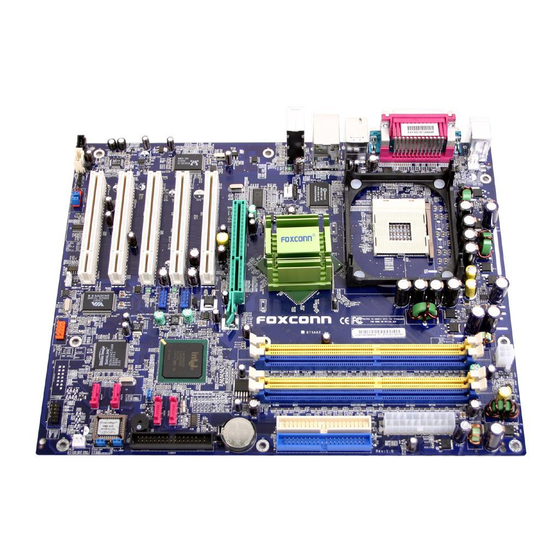
Page 13: 875A02 Layout
Chapter 1 Product Introduction 875A02 Layout 875A02 User Manual... - Page 14 PIO Modes 3 & 4 IDE devices. Both the primary (blue)and secondary (white) connectors are slotted to prevent incorrect insertion of the IDE ribbon cable. AGP slot This Accelerated Graphics Port (AGP) slot supports 1.5V AGP8X mode Graphic card for 3D graphical applications. 875A02 User Manual...
- Page 15 1394 controller (optional) VT6307 is the controller for IEEE1394a on Motherboard. The VT6307 is a complete small package single chip PCI solution at 400Mbps, low power seamless plug and play connections to the latest IEEE 1394 enabled devices 875A02 User Manual...
- Page 16 Super I/O functionality. The chip supports a high-performance floppy disk controller for a 360k/720K/1.44M/2.88M floppy disk drive, a multi- mode parallel port, two serial ports, the mouse and keyboard interface and the LPC (Low Pin Count) interface. 875A02 User Manual...
- Page 17 Chapter This chapter introduces the hardware installation process, including the installation of the CPU and memory. It also addresses the connection of your power supply, use of the rear panel connectors, connection of hard drive and floppy drive data cables, and setting up various other feature of the motherboard.
-
Page 18: Chapter 2 Installation Instructions
3. Hold components by their edges to avoid touching any exposed integrated circuits (ICs). 4. Whenever you uninstall a component, place it on a grounded anti-static pad or into the anti-static bag that it came in. 875A02 User Manual... -
Page 19: Cpu
3. When the CPU is in place, press it firmly on the socket while you push down the socket lever to secure the CPU. The lever clicks on the side tab to indicate that it is locked. 875A02 User Manual... - Page 20 3-pin terminal on the motherboard. Warning: Excessive temperatures will severely damage the CPU and system. Therefore, make sure that the cooling fan works nor- mally at all times in order to prevent overheating and damage. 875A02 User Manual...
- Page 21 Retention Hole Retention Lock Retention Hook snapped to the Retention Hole Warning: Keep the retention locks lifted upward while fitting the retention mechanism to the module base. 875A02 User Manual...
- Page 22 Chapter 2 Installation Instructions Attention: 1. Push down the locks on the retention mechanism to secure the heatsink and fan to the module base. 2. When secure,the retention locks should point to opposite directions. 875A02 User Manual...
- Page 23 1.Make sure to use only the tested and qualified CPUs listed above. Other CPUs manufactured by other vendors may not be suitable for this motherboard. 2.When use the Willamette CPU, please refer to the “CPU Model Selection Jumper: CN1” of page 39. 875A02 User Manual...
-
Page 24: Memory
184-pin footprint compared to the 168-pin of the SDR DIMM. Also, a DDR DIMM is single notched while an SDR DIMM is double notched. Therefore, a DDR DIMM is not backward compatible with SDR, and should be installed only in a socket specially designed for DDR DIMMs. 875A02 User Manual... - Page 25 See the following list of qualified vendors. The following table lists the PC3200/2700/2100 memory modules that have been tested and qualified for use with this motherboard. 875A02 User Manual...
- Page 26 PC2700 (DDR 333) 256M Hynix PC3200 (DDR 400) 256M Note: Make sure to use only the tested and qualified DDR DIMMS listed above. Other DDR DIMMs manufactured by other vendors may not be suitable for this motherboard. 875A02 User Manual...
- Page 27 6. When all four sockets are populated with 1GB DIMMs (total 4GB), the system may detect over 3GB (a little less than 4GB) to ICH5R resource allocation. 7. lt is recommended to use the yellow DIMM slots first. 875A02 User Manual...
- Page 28 3. The plastic clips at both sides of the DIMM slot will lock automatically. Note: Be sure to unplug the AC power supply before adding or re- moving expansion cards or other system peripherals, espe- cially the memory devices, otherwise your motherboard or the system memory might be seriously damaged. 875A02 User Manual...
-
Page 29: Power Supply
Attention: You have to press the power button for more than four seconds if you change the default Instant-off setting to “Delay 4 Sec” for the soft-off by Power Button option in the BIOS Power Management Setup. 875A02 User Manual... -
Page 30: Rear Panel Connectors
This motherboard includes one 25-pin mother connector for LPT. The par- allel port is a standard printer port which supports the enhanced parallel port (EPP), ECP mode, etc. USB 2.0 Ports These four Universal Serial Bus (USB) ports are available for connecting USB 2.0 devices. 875A02 User Manual... - Page 31 MIC input, as being shown in the following figure: Blue Green Center Front Left Front Right Rear Right Rear Left Subwoofer 875A02 User Manual...
-
Page 32: Other Connectors
Refer to the hard disk documentation for the jumper settings. Attention: Ribbon cables are directional, therefore, make sure to always connect with the cable on the same side as pin 1 of the PIDE/ SIDE or FDD connector on the motherboard. 875A02 User Manual... - Page 33 Power LED indicates the power supply status, and will be lit during normal system operation. The Power LED will blink while the system is in the S1 mode, and will be turned off when the system is in either S3 or S5 mode. 875A02 User Manual...
- Page 34 IrDA Header: IR The IrDA infrared transmission allows your computer to send and receive data via an infrared ray. The relevant parameters for the BIOS Integrated Peripherals should be set prior to using this function. 5V-SYS IRRX IRTX 875A02 User Manual...
- Page 35 1. You must install the driver before you can use the USB 2.0 function. 2. NEVER connect a 1394 cable to the F_USB1 or F_USB2 connectors. Doing so will damage the motherboard! 3. The USB cable is an optional item. 875A02 User Manual...
- Page 36 PC Health section of the BIOS. CPU_FAN GMCH_FAN +12V FAN1 Audio Connectors: CD_IN, AUX_IN To receive audio input from the CD-ROM, attach its audio connector to the CD_IN/ AUX_IN audio headers on the motherboard. CD_R CD_IN CD_L AUX_L AUX_IN AUX_R 875A02 User Manual...
- Page 37 PCI Card” to enabled in the “POWER MANAGEMENT SETUP” section of the CMOS SETUP. Save and exit, then boot the operating system once to make sure this function takes effect. Signal for waking up +5VSB 875A02 User Manual...
- Page 38 Parallel ATA interface. 3. The IAA-RAID driver is available for WinXP/2000 only. 4. RAID 0 and RAID 1 are supported. 5. Install WinXP Service Pack1 when using Serial ATA. 875A02 User Manual...
- Page 39 Following are the Parallel ATA and Serial ATA device configurations supported by Intel ICH5R specifications. P-ATA S-ATA Operating System Primary Secondary Port 0 Port1 (2 devices) (2 devices) (1 device) (1 device) 1.Windows 2000/XP 2.Windows 98/ME/NT4.0 Configuration 1 Configuration 2 Configuration 3 NOTE: Supported Disabled 875A02 User Manual...
- Page 40 The SPDIF_OUT output is capable of providing digital or 6 channel audio to external speakers, or compressed AC3 data to an external Dolby digital decoder. The motherboard is equipped with one bracket. SPDIF_OUT K E Y SPDIF_OUT 875A02 User Manual...
-
Page 41: Expansion Slots
Please read carefully the instructions provided for such cards, and install and set the necessary hardware and software for such cards, such as the jumper or BIOS settings. PCI Slot 875A02 User Manual... - Page 42 The motherboard may be damaged if a 3.3V AGP card is used. Make sure that your AGP card is 1.5V specification. Note the notches on the card golden fingers to ensure that they fit the AGP slot on your motherboard. 875A02 User Manual...
- Page 43 QDI FX5200 128MB DDR ASUS ASUS V9280/TD 8X 128MB DDR Note: Make sure to use only the tested and qualified AGP cards listed above. Other AGP cards manufactured by other vendors may not be suitable for this motherboard. 875A02 User Manual...
-
Page 44: Jumpers
Users should refer to this when adjusting jumper settings. Jumper Diagram Definition Description Set pin 1 and pin 2 closed Set pin 2 and pin 3 closed Closed Set the pin closed Open Set the pin opened 875A02 User Manual... - Page 45 3. Turn the AC power supply back on. Normal status (default) Clear CMOS CLS_CMOS (Unplug the AC power supply) Warning: 1. Disconnect the power cable before adjusting the jumper settings. 2. Do not clear the CMOS while the system is turned on. 875A02 User Manual...
- Page 46 LAN Disabled Jumper: LAN_DIS Close pins 1 and 2 on LAN_DIS and enable the onboard lan. If LAN_DIS is set pins 2 and 3 at closed, then the onboard lan is disabled. Onboard Enable LAN_DIS Onboard Disable LAN_DIS 875A02 User Manual...
- Page 47 Chapter 2 Installation Instructions CPU Model Selection Jumper: CN1 The default status for CN1 is Open, which supports the Prescott and Northwood CPU. If CN1 is set at Closed, then it supports the Willamette CPU. Closed Open (Default) 875A02 User Manual...
- Page 48 BIOS setting. Pressing the power switch for more than 4 seconds lets the system enter the soft-off mode regardless of the BIOS setting. 875A02 User Manual...
- Page 49 Chapter This chapter introduces the 875A02 motherboard’s CMOS Setup program, which allows users to configure optimized system settings. You have to run the Setup Program when the following cases occur: 1. An error message appears on the screen during the system POST process.
-
Page 50: Chapter 3 Bios Description
The items in the BIOS Setup main menu are explained below: Standard CMOS Features The basic system configuration can be set up through this menu. BIOS Features The general system features can be set up through this menu. 875A02 User Manual... - Page 51 The user password can be set up through this menu. Save & Exit Setup Save the change(s) made to the CMOS settings and exit Setup. Exit Without Saving Abandon the change(s) made to the CMOS settings and exit Setup. 875A02 User Manual...
-
Page 52: Standard Cmos Features Setup
HDD; when “Manual” is selected and the Access Mode is changed to CHS, the system will request you to key in the following HDD parameters: Cylinder number of cylinders Head number of heads Precomp write pre-compensation Landing Zone Landing Zone Sector number of sectors 875A02 User Manual... - Page 53 The system will stop when any error other than keyboard error occurs All, But Diskette The system will stop when any error other than disk error occurs All, But Disk/Key The system will stop when any error other than keyboard or disk error occurs 875A02 User Manual...
- Page 54 Base Memory The basic memory capacity loaded in the system is determined by BIOS during the POST. Extended Memory The extended memory capacity is determined by BIOS during the POST. Total Memory The total of all memory capacities. 875A02 User Manual...
-
Page 55: Bios Features
133 MHz to 165 MHz; FSB 800 MHz CPU, the setting range is from 200 MHz to 232 MHz. Warning: Be sure your selection is right. CPU over speed will be dangerous! We will not be responsible for any damages caused. 875A02 User Manual... -
Page 56: Advanced Bios Features
Threading has been installed. Quick Power On Self Test (Default: Enabled) With this function enabled, the system will skip the normal test while starting up, therefore reducing the overall start up time. The available setting values are: Disabled and Enabled. 875A02 User Manual... - Page 57 Disabled, the 2 subsequent options will be closed. Typematic Rate (Chars/Sec) (Default: 6) Used to set the repeat rate for keyboard input of the same letter. Typematic Delay (Msec) (Default: 250) Used to set the repeat keyboard input rate when pressing a key continuously. 875A02 User Manual...
- Page 58 FDD Set whether BIOS reports Windows 95 or not loading floppy disk drive. The available setting values are: No and Yes. Small Logo (EPA) Show (Default: Disabled) Determines whether the small logo (EPA) will be displayed during system startup. The available setting values are: Disabled and Enabled. 875A02 User Manual...
- Page 59 This option is used to set up the time for CPU to enter the energy-saving mode. Thermal Management (Default: Thermal Monitor 1) This option is used to manage Prescott CPU thermal. Note: This function will not be displayed until a Prescott CPU has been installed. 875A02 User Manual...
-
Page 60: Advanced Chipset Features
Note: The operating frequency will be 320MHz when a 800MHz CPU and a DDR333MHz are used jointly. System BIOS Cacheable (Default: Enabled) This option is used to determine whether the system BIOS is written into the buffer memory. The available setting values are: Disabled and Enabled. 875A02 User Manual... - Page 61 ECC and Non-ECC. Fast Chip Select (Default: Auto) This option allows you to set the Intel PAT function, select “Enabled” for the ® Intel PAT function is OK. The available setting values are: Auto and Enabled. ® 875A02 User Manual...
-
Page 62: Integrated Peripherals
This option is used to set the PIO transfer mode under the IDE Primary Master/Slave Controller. PIO transfer mode options include Auto/0/1/2/3/4. Set the transfer mode according to the IDE specification. It is recommended to set it to Auto for the auto-test by BIOS. 875A02 User Manual... - Page 63 SATA Only selected, the SATA HDD acts as both the primary and secondary drive. With the mode set to SATA 0/1 Master and the option SATA Enhanced Mode selected, both IDE ports and both SATA ports will be available. 875A02 User Manual...
- Page 64 This option allows you to enable or disable the onboard LAN function. The available setting values are: Disabled and Enabled. Onboard Lan Boot ROM (Default: Disabled) This option allows you to enable or disable the onboard Lan Boot ROM function. The available setting values are: Disabled and Enabled. 875A02 User Manual...
- Page 65 IrDA, and ASKIR. The setting value is determined by the infrared module installed on the board. When it is set to IrDA and ASKIR, the UART supports communication with the MB by means of the infrared module; when it is set to Normal, the infrared function is unavailable. 875A02 User Manual...
- Page 66 This option is used to set what action the PC will take with the power supply when it resumes after a sudden power failure. The available options are Off (remain in turnoff status), On (restart) and Former-Sts (resume with the previous status). 875A02 User Manual...
-
Page 67: Power Management Setup
No (this function invalid). Power Management (default: User Define) This option is used to set the power management scheme. Available settings are: User Define (defined by user), Min Saving (minimum saving mode), and Max Saving (maximum saving mode). 875A02 User Manual... - Page 68 ATX. When “Instant - Off” is selected, press the power switch to immediately turn off power. When “Delay 4 Sec” is selected, press the power button for four seconds to turn off power. 875A02 User Manual...
- Page 69 This option is used to set the timing for the start-up date. The setting values contain 0-31. Time (hh:mm:ss) Alarm This option is used to set the timing for the start-up time. The setting values contain hh: 0 – 23; mm:0 – 59; ss:0 – 59. 875A02 User Manual...
- Page 70 The setting values are Disabled and Enabled. PCI PIRQ[A-D] # (default: Disabled) This option is used to set the system to up by PCI equipment. be waked The setting values are Disabled and Enabled. 875A02 User Manual...
-
Page 71: Pnp/Pci Configuration Setup
The setting values are Disabled and Enabled. INT Pin 1-8 Assignment (default: Auto) This option is used to distribute the interruption requirements of various PCI equipment. 875A02 User Manual... -
Page 72: Pc Health Status
This option is used to set upper limitation of system temperature. When the temperature is higher than setting values, motherboard will automatically cut off the power of computer. The setting values are Disabled and 60 C/140 C/167 875A02 User Manual... -
Page 73: Frequency/Voltage Control
0.35%, 0.50%, 0.75% and 1.00%. Warning: Please carefully set working frequency of CPU. We suggest not adjust frequency of CPU higher than normal working range at random. This company will not be responsible for any dam- age arisen in this case. 875A02 User Manual... -
Page 74: Load Fail-Safe Defaults
In this case, you can freely enter into system and CMOS setting program. PASS WORD DISABLED!!! Press any key to continue... 875A02 User Manual... -
Page 75: Save & Exit Setup
Select this option and press Enter, it will show the following message in the center of screen: Quit Without Saving (Y/N)? At this time, press <Y> to exit CMOS but it does not save your amendment in CMOS; press <N>/<ESC> to return main menu. 875A02 User Manual... - Page 76 Chapter This chapter will introduce how to install driver software and application tool software of motherboard, let your motherboard exert the largest effect. This chapter provides the following information: Introduction to content of motherboard driver CD Start to install driver and software Install Chipset Software Install IAA-RAID Install USB2.0 driver...
-
Page 77: Chapter 4 Driver Cd Introduction
C. Norton Internet Security 2004 3.Browse CD Click here to browse CD content. 4. Homepage Click here to visit Foxconn motherboard homepage. Note: 1. Install the latest patch first if your OS is Windows XP or Windows 2000. 2. Follow the CD screen order to install your motherboard drivers. -
Page 78: Start To Install Driver
Select <Install Driver>, and click to enter the install driver screen. You can select the driver that you want to install and begin the setup steps. Read this guide Note: The following setup steps are based on Windows XP environment. There may be some differences with other operating systems. 875A02 User Manual... -
Page 79: Install Chipset Software
Install Chipset Software Select <Install Driver> from the main menu and enter the main driver setup menu (as shown in fig. 1). Click <Chipset Software> to start the installation. Click here Click here Click here Click here Click here 875A02 User Manual... -
Page 80: Install Iaa-Raid (Optional)
From the main menu, select <Install Driver> as shown in following fig. 1. click <IAA RAID> to start the setup. Note: IAA RAID is only applicable for the ICH5R chipset. Click here Click here Click here Click here Click here Click here Click here 875A02 User Manual... -
Page 81: Install Usb2.0 Driver
Read this guide Note: Use of USB 2.0 requires the support of your operating system. If you are using Windows 98 or Windows Me, you will need to up- grade your operating system to use USB2.0. 875A02 User Manual... -
Page 82: Install Lan Driver (For Realtek 10/100/1000M Lan)
Chapter 4 Driver CD Introduction Install LAN Driver (For Realtek 10/100/1000M LAN) From the main menu, select <Install Driver> as shown in fig. 1. click <LAN Driver> to start the setup. Click here Click here Click here 875A02 User Manual... -
Page 83: Install And Use 4- Or 6- Channel Audio Function
4).Play Karaoke 1).Install Audio Driver Before using the 4-/6- channel audio functions, you must first install the driver for the Realtek ALC650 chip. Install the driver according to the procedure described below: Click here Click here Click here 875A02 User Manual... - Page 84 Description: all Line Out, Line In and Microphone functions exist in 2- channel mode. 4-Channel Analog Audio Interface Line Out (rear channels) Line Out (front channels) Microphone Description: in the 4-channel setting, Line In is changed to Line Out function. 875A02 User Manual...
- Page 85 The blank pin of the SPDIF connection cable corresponds to the 9 pin of the 6CH_Bracket. Description: for digital audio output, use the provided SPDIF interface. Con- nect the coaxial SPDIF joint to the coaxial SPDIF jack. 875A02 User Manual...
- Page 86 B. In the drop-down menu of sound effect item, select the desired surround sound effect. Click here the pull-down menu will appear. C. Click the Speaker Configuration tab. Click here 875A02 User Manual...
- Page 87 Testing Each Speaker 1. Click the audio icon from the window tray at the bottom of the screen. 2. Click the Speaker Test tab. 3. The following window appears. Center Front Left Front Right Rear Left Rear Right Subwoofer 875A02 User Manual...
- Page 88 “Speaker configuration” list. Play Karaoke: A. Click audio icon in Windows taskbar in the lower-right of the screen. B. Ensure that “Sound Effect” is selected. C. Select “Sound Effect” in “Karaoke”. Click here D. Click “OK”. 875A02 User Manual...
-
Page 89: Install Sil3112 Sataraid
<Sil3112 SATARaid> to open the Sil3112 SATARaid setup window. Please read the setup directions carefully and select the installation method corresponding to the operating system that you are currently using. Note: Sil3112 SATARaid is only applicable for the Silicon 3112A controller. 875A02 User Manual... -
Page 90: Install Directx
Chapter 4 Driver CD Introduction Install DirectX From the main menu, select <Install Driver> (as shown in following fig. 1), and click <DirectX 9.0b> to start the setup. Click here Click here Click here Click here 875A02 User Manual... -
Page 91: Install Norton Internet Security 2004
Click <Norton Internet Security 2004> to start the setup. Click here Click here Click here Click here Click here Note: If your system is Windows 98 or Window ME, please make sure that your Internet Explorer version is 5.01 with service pack 2 or higher. 875A02 User Manual... - Page 92 Chapter 4 Driver CD Introduction Chapter This chapter introduces the pertain to software. This chapter includes the following information: SuperStep SuperLogo SuperUpdate 875A02 User Manual...
-
Page 93: Directions For Bundled Software
3. Adjusts the CPU frequency to speed up your system and achieve better system performance. 4. Simple and easy to operate, with a user-friendly graphics interface. Using the SuperStep: Go to Fan page System Fan1 speed Link to FOXCONN Website CPU Fan speed Exit Program Minimize Window... - Page 94 (lower limit) Go to Temperature page Current CPU Adjust CPU tem- Temperature perature warning criteria Current system Adjust system Temperature temperature warning criteria Apply the adjust- Reset the warn- ments ing criteria to default settings 875A02 User Manual...
- Page 95 Adjust the Adjust the CPU CPU Ratio Reset to the default Apply the adjustments settings Go to setting page Check for the system to auto- matically provide warning message Reset to the Apply the default settings changes 875A02 User Manual...
-
Page 96: Superlogo
The best resolution is 136x84 for top-right logo and 640x480 or 800x600 for full screen logo. Using the SuperLogo: Go to ROM Info page Display the Flash Information Link to Foxconn website Exit Program Minimize Window SuperLogo on-line Help About SuperLogo... - Page 97 Browse a BIN file BIOS image for updating BIOS file location Follow the Wizard to complete the BIOS function Go to Backup page Backup whole Backup Logo BIOS image Follow the Wizard to complete the backup function 875A02 User Manual...
-
Page 98: Superupdate
3. Simple and easy to operate, with a user-friendly graphics interface. Using SuperUpdate: Browse BIOS bin file Perform the BIOS update from local HDD from local image Link to FOXCONN Website Exit Program Minimize Window SuperUpdate on-line Help About SuperUpdate Upgrating BIOS via... - Page 99 Chapter 5 Directions for Bundled Software Update BIOS from local image: 1. Click <Backup> to backup the current BIOS to an image file. 2. Click <Load> to load the BIOS file. 875A02 User Manual...
- Page 100 Chapter 5 Directions for Bundled Software 3. Click <Update>. 4. Click <Yes>. 875A02 User Manual...
- Page 101 Chapter 5 Directions for Bundled Software 5. Click <OK>. 6. Click <OK> to update the current BIOS. 7. Click <Restart >. 875A02 User Manual...
- Page 102 Chapter 5 Directions for Bundled Software Update BIOS On-line: 1. Click <Liveupdate> to automatically update the BIOS from the internet. 2. Click <Yes> to backup the current BIOS. 875A02 User Manual...
- Page 103 Chapter 5 Directions for Bundled Software 3. Click <Ok> to update BIOS. 4. Click <Restart >. 875A02 User Manual...
- Page 104 This chapter will introduce new functions of BIOS and how to use them in detail. It can further exert the max potential of motherboard to bring you super-value enjoyment. This chapter introduces the following new functions of BIOS: SuperSpeed SuperBoot SuperBIOS-Protect SuperRecovery 875A02 User Manual...
-
Page 105: Chapter 6 Special Bios Feature
Save and exit BIOS Setup, your system will now boot successfully. SuperSpeed Setup Menu BIOS provides you a set of basic values for your processor selection instead of the jumper settings. The processor speed can be manually set from the <BIOS Features> menu screen. BIOS Main menu 875A02 User Manual... - Page 106 Chapter 6 Special BIOS Feature BIOS Features Menu Warning: Do not set CPU frequency higher than its working frequency. If you do, we can not be responsible for any damages caused. 875A02 User Manual...
-
Page 107: Superboot
OS. SuperBoot is easy to use. Choose the right option in the CMOS SETUP (refer to Foxconn Innovation features) and the sys- tem can boot up quickly and easily. SuperBoot saves the information from the PC’s first normal boot-up, and there restores all the parameters for the system... -
Page 108: Superbios-Protect
2. Set the jumper (FWH_EN) as Flash Write Enabled (pin 1-2 closed), mean- while set SuperBIOS-Protect as Disabled in CMOS Setup. In this way, the BIOS can be overwritten. 3. FWH_EN Default is enabled. 875A02 User Manual... -
Page 109: Superrecovery
You should enter the CMOS setup interface first by pressing <DEL> during POST (Power On Self Test). Then select the “Recovery Easy Hotkey” option to adjust the hotkey settings in the “BIOS Features” menu. There are 12 options: LSHIFT (Left Shift)+F1~F12. LSHIFT+F12 is the default. 875A02 User Manual... - Page 110 3) Only one HDD can be operated at a time; Note: If you have assigned a password to the selected HDD, you will be prompted to provide it before proceeding. 875A02 User Manual...
- Page 111 2) The system will then prompt you to Enter “Y” or “N” for confirmation. Press “Y” to restart the computer, and the division for hidden partition will be taken into effect after the system is restarted. 875A02 User Manual...
- Page 112 “Y” to confirm, the system will be restarted to release the hidden partition. But the released partition is still unavailable for you after the system is restarted. It’s necessary for you to enable it by using FDISK, PQMAGIC, or some other tools. 875A02 User Manual...
- Page 113 1) Support backing up of the CMOS data. 2) The backing up or recovery of CMOS data should be operated on a Motherboard of the same model. 2. Backup Partition Table: This function can help to backup all partition tables including extended partitions. 875A02 User Manual...
- Page 114 1) If there are active partitions (system partition), you can choose an active partition or the whole disk for backing up. But only one can be taken between the two choices. Old data will be replaced by the newly backed 2) Backing up with the progress bar showing. 875A02 User Manual...
- Page 115 Select RECOVERY to enter the Recovery interface. The following sub-functions are available : as RECOVER CMOS SETUP, RECOVER PARTITION TABLE and RECOVER HARDDISK DATA. You can switch the highlight bar by pressing the arrow keys to make a selection and press “Enter” to confirm your selection. 875A02 User Manual...
- Page 116 Chapter 6 Special BIOS Feature 1. Recover CMOS Setup: This function can help to restore the latest backup of CMOS settings you made. 2. Recover Partition Table: This function can help to recover all partition tables including extended partitions. 875A02 User Manual...
- Page 117 1) Enter the old password first. Press ‘ENTER’ if password is null. 2) Enter the new password. Then enter the same again to confirm it. 3) Press “Enter” for null password. 4) The password will be saved in the hidden partition. 875A02 User Manual...
Need help?
Do you have a question about the 875A02 and is the answer not in the manual?
Questions and answers