Table of Contents
Advertisement
Statement:
This manual is the intellectual property of FOXCONN Inc. Although the
information in this manual may be changed or modified at any time,
FOXCONN does not obligate itself to inform the user of these changes.
Trademark:
All trademarks are the property of their respective owners.
Version:
User Manual V1.0 in English for NF4UK8AA series motherboard.
P/N: 91-181-CK8-AA-0E
Symbol description:
Note: refers to important information that can help you to use motherboard
better.
Attention: indicates that it may damage hardware or cause data loss,
and tells you how to avoid such problems.
Warning: means that a potential risk of property damage or physical
injury exists.
More information:
If you want more information about our products, please visit the following
website: http://www.foxconnchannel.com
1
2005-1-5, 9:19
Advertisement
Table of Contents

Related Manuals for Foxconn NF4UK8AA series


Summary of Contents for Foxconn NF4UK8AA series
- Page 1 This manual is the intellectual property of FOXCONN Inc. Although the information in this manual may be changed or modified at any time, FOXCONN does not obligate itself to inform the user of these changes. Trademark: All trademarks are the property of their respective owners.
- Page 2 Item Checklist: Thank for your purchasing WinFast NF4UK8AA series motherboard. Please check the package; if there are missing or damaged items, contact your distributor as soon as possible. NF4UK8AA Series Motherboard (x1) WinFast Utility CD (x1) NVRAID Driver Disk (x1) (optional) User Manual (x1) IDE Cable (x2) FDD Cable (x1)
-
Page 3: Declaration Of Conformity
Declaration of conformity HON HAI PRECISION INDUSTRY COMPANY LTD 66 , CHUNG SHAN RD., TU-CHENG INDUSTRIAL DISTRICT, TAIPEI HSIEN, TAIWAN, R.O.C. declares that the product Motherboard NF4UK8AA is in conformity with (reference to the specification under which conformity is declared in accordance with 89/336 EEC-EMC Directive) EN 55022/A1: 2000 Limits and methods of measurements of radio disturbance... - Page 4 Declaration of conformity Supplementary Information: This device complies with Part 15 of the FCC Rules. Operation is subject to the following two conditions : (1) this device may not cause harmful interference, and (2) this device must accept any interference received, including interference that may cause undesired operation.
-
Page 5: Table Of Contents
Table of Contents Chapter Product Introduction Main Features ....................2 Motherboard Layout ..................4 Chapter Installation Instructions CPU ......................7 Memory ...................... 10 Power Supply .................... 13 Rear Panel Connectors ................14 Other Connectors ..................15 Expansion Slots ..................19 Jumpers ..................... - Page 6 Table of Contents Chapter Driver CD Introduction Utility CD content ..................Start to install drivers ................. Install USB2.0 Driver .................. 54 ..................55 Install Norton Internet Security ..............56 Chapter NVIDIA RAID Introduction Basic Configuration Introductions .............. 59 Setting up the BIOS ..................60 Entering the RAID BIOS Setup ..............
- Page 7 Warning: 1. Attach the CPU and heatsink using silica gel to ensure full contact. 2. It is suggested to select high-quality, certified fans in order to avoid damage to the motherboard and CPU due to high temperature. 3. Never turn on the machine if the CPU fan is not properly installed. 4.
- Page 8 This manual is suitable for motherboard of NF4UK8AA series. Each motherboard is carefully designed for the PC user who wants diverse features. with onboard 100M LAN with onboard 1G LAN with 6-channel audio with 8-channel audio with 1394 with SATA with RAID You can find PPID label on the motherboard.
- Page 9 Chapter T h a n k y o u f o r b u y i n g W i n F a s t N F 4 U K 8 A A s e r i e s motherboard. This series of motherboard is one of our new products, and offers superior performance, reliability and quality, at a reasonable price.
-
Page 10: Chapter Product Introduction
Chapter 1 Product Introduction Main Features Size: ATX form factor of 12” x 9.6” Microprocessor: Supports Socket-939 for AMD K8 Athlon 64FX/Athlon 64 processors HyperTransport Technology: 16 x 16 link running at 1GHz for extremely high throughput (8.0GB/sec) Differential lines with low voltage swings Chipset: NVIDIA Chipset: NVIDIA nForce4 Ultra System Memory... - Page 11 Chapter 1 Product Introduction With rate of transmission at 400Mbps Self-configured addressing Supports two independent 1394 units synchronously at most, such as HDD, CD-ROM Onboard LAN (-K) Supports10/100/1000 (-K) Mbps Ethernet LAN interface built-in on board Onboard Audio Supports 8-channel audio Supports SPDIF output Supports Universal Audio Jack (UAJ) Supports high quality differential CD input...
-
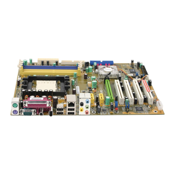
Page 12: Motherboard Layout
Chapter 1 Product Introduction Motherboard Layout 20 21 22 23 1. PCI Express x1 slots 2. CD_IN connector 3. Front Audio connector 4. SPDIF_OUT connector 5. PE_REFCLK select jumper 6. Termination enable jumper 7. PCI slots 8. Auxiliary PEX power connector 9. - Page 13 Chapter 1 Product Introduction Chapter This chapter introduces the hardware installation process, including the installation of the CPU and memory. It also addresses the connection of your power supply, use of the rear panel connectors, connection of hard drive and floppy drive data cables, and setting up various other feature of the motherboard.
- Page 14 Chapter 2 Installation Instructions Take note of the following precautions before you install components or change settings. 1. Use a grounded wrist strap or touch a safely grounded object, such as an attached power supply, before handling components to avoid damaging them due to static electricity.
-
Page 15: Cpu
Chapter 2 Installation Instructions This motherboard supports Athlon 64FX/Athlon 64 processors running at 1GHz for extremely high throughput (8.0GB/sec) and Hyper Transport Technology. Attention: The CPU pins must be properly aligned with the holes in the socket, otherwise the CPU may be damaged. Installation of CPU Follow these steps to install the CPU. - Page 16 Chapter 2 Installation Instructions Installation of CPU Fan New technology allows processors to run at higher and higher frequencies. To avoid problems arising from high-speed operation, for example, overheating, you need to install the proper fan. The following procedure is provided for reference only, please refer to your CPU fan user guide for the actual procedure.
- Page 17 Chapter 2 Installation Instructions 3. Place the cooling set onto the re- 4. Align the other end of the reten- tention mechanism. Attach one end tion bracket to fasten the cooling of the retention bracket to retention set on the top of the retention mechanism.
-
Page 18: Memory
Chapter 2 Installation Instructions CPU Qualified Vendor List The following table lists the CPUs that have been tested and qualified for use with this motherboard. Package Cache Size Frequency Model Number Socket 512KB 2200 MHz Athlon64 3500+ Socket 512KB 2400 MHz Athlon64 3800+ Socket 2400 MHz... - Page 19 Chapter 2 Installation Instructions Note: Be sure to unplug the AC power supply before adding or re- moving expansion cards or other system peripherals, espe- cially the memory devices, otherwise your motherboard or the system memory might be seriously damaged. Recommended Memory Configurations The following table list is the recommended memory configurations.
- Page 20 Chapter 2 Installation Instructions Memory Qualified Vendor List The following table list is the memory modules that have been tested and qualified for use with this motherboard. Vendor Type Size INFINEON PC3200(DDR400) 256M INFINEON PC2700(DDR333) SAMSUNG PC3200(DDR400) 256M KINGMAX PC2100(DDR266) 256M PC2700(DDR333) 256M...
-
Page 21: Power Supply
Chapter 2 Installation Instructions Power Supply This motherboard uses an ATX power supply. In order to avoid damaging any devices, make sure that they have been installed properly prior to connecting the power supply. +5V_AUX +12V +3.3V +12V PWROK ATX Power Connector: PWR1 PWR1 is the ATX power supply connector. -
Page 22: Rear Panel Connectors
Chapter 2 Installation Instructions Rear Panel Connectors This motherboard provides the following ports as below: Parallel Port LAN Port (-K) (Printer Port) Rear L i n e - i n / Side PS/2 Mouse Port Line-out/ Front PS/2 Keyboard Port Microphone CEN/LFE COM1... -
Page 23: Other Connectors
Chapter 2 Installation Instructions Rear, Line in/side, Line out, Microphone, CEN/LFE When using a 2-channel sound source, the Line out jack is used to connect to speaker or headphone; the Line in jack connects to an external CD player, tape player or other audio device. The Microphone jack is used to connect to the microphone. - Page 24 Chapter 2 Installation Instructions Front Panel Connector: FP IDE_LED PLED This motherboard includes one connector for con- necting the front panel switch and LED indicator. RESET PWRBTN# Empty Hard Disk LED Connector (IDE_LED) Attach the connector to the IDE_LED on the front panel of the case; the LED will flash while the HDD is in operation.
- Page 25 Chapter 2 Installation Instructions Fan Connectors: CPU_FAN, FAN1, FAN2 There are three fan connectors on this motherboard. SENSE +12V +12V +12V SENSE SENSE CPU_FAN FAN1 FAN2 Audio Connector: CD_IN CD_IN is Sony standard CD audio connectors, CD_R to receive audio input from the CD-ROM, attach CD_L its audio connector to the CD_IN audio connec- tors on the motherboard.
- Page 26 Chapter 2 Installation Instructions Speaker Connector SPKJ The speaker connector is used to connect EMPTY speaker of the chassis SPK(Pull high) SPEAKER SPDIF Out Connector: SPDIF_OUT The S/PDIF out connector is capable of provid- EMPTY ing digital audio to external speakers or com- SPDIF-OUT pressed AC3 data to an external Dolby digital decoder.
-
Page 27: Expansion Slots
Chapter 2 Installation Instructions Expansion Slots This motherboard includes four 32-bit Master PCI bus slots, two PCI Express x1 slots, and one PCI Express x16 slot. PCI Slots The expansion card can be installed in the PCI slot. When you install or take out such card, you must make sure that the power plug has been pulled out. - Page 28 Chapter 2 Installation Instructions Installing an expansion card 1. Before installing the expansion card, read the documentation that came with it and make the necessary hardware settings for the card. 2. Make sure to unplug the power cord before adding or removing expansion cards.
-
Page 29: Jumpers
Chapter 2 Installation Instructions Jumpers Users can change the jumper settings on this motherboard if necessary. This section explains how to use the various functions of this motherboard by chang- ing the jumper settings. Users should read the following contents carefully prior to modifying any jumper settings. - Page 30 Chapter 2 Installation Instructions Warning: 1. Disconnect the power cable before adjusting the jumper settings. 2. DO NOT clear the CMOS while the system is turned on. BIOS TBL ENABLE Jumper: JP1 The system cannot boot, if the BIOS failed to be BIOS TBL flashed in conventional flash BIOS process.
- Page 31 Chapter 2 Installation Instructions PE_REFCLK Select Jumper: J3A1 External clock This jumper is used to select the resource for PCI reference Express PLL reference clock. Internal clock reference (Default) PE_REFCLK Select Jumper Common Common Mode Level Select Jumper: J1G1 mode above This jumper is used to select common-mode level VDD/2 range for PCI Express external reference clock input...
- Page 32 Chapter 2 Installation Instructions Starting up for the first time 1. After making all the connections, replace the system case cover. 2. Make sure that all switches are turned off. 3. Turn on the devices in the following order. Monitor External SCSI devices (starting with the last device on the chain) System power 4.
- Page 33 Chapter This chapter tells how to change system settings through the BIOS Setup menus. Detailed descriptions of the BIOS param- eters are also provided. You have to run the Setup Program when the following cases occur: 1. An error message appears on the screen during the system POST process.
-
Page 34: Chapter Bios Description
Chapter 3 BIOS Description Enter BIOS Setup The BIOS is the communication bridge between hardware and software, correctly setting up the BIOS parameters is critical to maintain optimal system performance. Power on the computer, when the following message briefly appears at the bottom of the screen during the POST (Power On Self Test), press the <Del>... - Page 35 Chapter 3 BIOS Description SuperBIOS Features The general system features can be set up through this menu. Advanced BIOS Features The advanced system features can be set up through this menu. Advanced Chipset Features The values for the chipset can be changed through this menu, and the sys- tem performance can be optimized.
-
Page 36: Standard Cmos Features
Chapter 3 BIOS Description Standard CMOS Features This sub-menu is used to set up the standard CMOS features, such as the date, time, HDD model and so on. Use the arrow keys select the item to set up, and then use the <PgUp> or <PgDn> key to choose the setting values. Standard CMOS Features Menu Date This item allows you to set the desired date (usually as the current date) with... - Page 37 Chapter 3 BIOS Description Award (Phoenix) BIOS can support 4 HDD modes: CHS, LBA and Large or Auto mode. For HDD<528MB For HDD>528MB & supporting LBA (Logical Block Addressing) Large For HDD>528MB but not supporting LBA Auto Recommended mode Drive A/B This item allows you to select the kind of FDD to be installed, including [None], [360K, 5.25in], [1.2M, 5.25in], [720K, 3.5in], [1.44M, 3.5in] and [2.88 M, 3.5in].
- Page 38 Chapter 3 BIOS Description Memory This is a Displays-Only Category, determined by POST (Power On Self Test) of the BIOS. Base Memory The BIOS POST will determine the amount of base (or conventional) memory installed in the system. Extended Memory The BIOS determines how much extended memory is present during the POST.
-
Page 39: Superbios Features
Chapter 3 BIOS Description SuperBIOS Features SuperBIOS Features Menu [SuperBoot] SuperBoot (Default: Disabled) SuperBoot allows system-relevant information to be stored in CMOS upon the first normal startup of your PC, and the relevant parameters will be restored to help the system start up more quickly on each subsequent startup. [SuperBIOS-Protect] SuperBIOS-Protect (Default: Disabled) SuperBIOS-Protect function protects your PC from being affected by viruses, e.g. -
Page 40: Advanced Bios Features
Chapter 3 BIOS Description Advanced BIOS Features Advanced BIOS Features Menu Hard Disk Boot Priority This item is used to select the priority for HDD startup. After pressing <Enter>, you can select the HDD using the <PageUp>/<PageDn> or Up/Down arrow keys, and change the HDD priority using <+> or <->. To exit this option, press <Esc>. - Page 41 Chapter 3 BIOS Description Boot Up Floppy Seek (Default: Disabled) If it is set to Enabled, BIOS will activate the floppy drive during the system boot, and the drive’s indicator will flash after the activation. The magnetic head will move back and forth from A to B. Boot Up NumLock Status (Default: On) This item defines if the keyboard Num Lock key is active when your system is started.
-
Page 42: Advanced Chipset Features
Chapter 3 BIOS Description Advanced Chipset Features Advanced Chipset Features Menu HT Frequency (Default: 5x) This item specifies the maximum operating frequency of the link’s transmitter clock. HT Width (Default: 16, 16) This item specifies the maximum up and down bandwidth of the link’s transmitter. - Page 43 Chapter 3 BIOS Description CPU Thermal-Throttling (Default: 50.0%) This item is used to specify the CPU speed (at percentage) to slow down the CPU when it reaches the predetermined overheated temperature. System BIOS Cacheable (Default: Disabled) Select “Enabled” to allow catching of the system BIOS which may improve per- formance.
- Page 44 Chapter 3 BIOS Description Min RAS# active time (Tras) (Default: Auto) This item determines the time RAS takes to read from and write to a memory cell. Row Precharge Time (Trp) (Default: Auto) This item controls the number of cycles for Row Address Strobe (RAS) to be allowed to precharge.
-
Page 45: Integrated Peripherals
Chapter 3 BIOS Description Integrated Peripherals Integrated Peripherals Menu IDE Function Setup Press <Enter> to set the items about IDE function. Please refer to page 40. RAID Config Press <Enter> to set RAID Config. Please refer to page 41. Onchip USB (Default: V1.1+V2.0) This item is used to enable or disable the onboard USB controller. - Page 46 Chapter 3 BIOS Description USB Asyn Data Reads (Default: non-ISO Queue) This item is used to set the USB Asyn Data Reads. AC97 Audio (Default: Auto) This item is used to set whether onboard AC97 audio is enabled. Dis- abled the controller if you want to use other controller cards to connect an audio device.
- Page 47 Chapter 3 BIOS Description UART Mode Select (Default: IrDA) Use this item to select the UART mode. Setting values include Normal, IrDA, ASKIR. The setting value is determined by the infrared module installed on the board. UR2 Duplex Mode (Default: Half) This item is available when UART Mode Select is set to either ASKIR or IrDA.
- Page 48 Chapter 3 BIOS Description IDE Function Setup Menu OnChip IDE Channel0/1 (Default: Enabled) The integrated peripheral controller contains an IDE interface with support for two IDE channels. Choose Enabled to activate each channel separately. Primary/Secondary Master/Slave PIO (Default: Auto) These four items let you assign which kind of PIO (Programmer Input/Output) is used by IDE devices.
- Page 49 Chapter 3 BIOS Description RAID Config Menu RAID Enable (Default: Disabled) This item is available for you to enable or disable the onboard RAID function. IDE Primary/Secondary/Mater/Slave RAID (Default: Disabled) These features allow user to enable or disable the RAID function for each IDE hard disk drive.
-
Page 50: Power Management Setup
Chapter 3 BIOS Description Power Management Setup Power Management Setup Menu ACPI function (Default: Enabled) ACPI stands for “Advanced Configuration and Power Interface”. ACPI is a standard that defines power and configuration management interfaces be- tween an operating system and the BIOS. In other words, it is a standard that describes how computer components work together to manage system hardware. - Page 51 Chapter 3 BIOS Description HDD Power Down (Default: Disabled) If HDD is not detected for the length of time specified in this field, the hard disk drive will be powered down while all other devices remain active. HDD Down In Suspend (Default: Disabled) This item determines whether the hard disk drive will be turned off during suspend mode.
- Page 52 Chapter 3 BIOS Description Day of Month Alarm When the Power-On by Alarm set as Enabled, this option will be modified. It is used to set the timing for the start-up date. Time (hh:mm:ss) Alarm When the Power-On by Alarm set as Enabled, this option will be modified. It is used to set the timing for the start-up time.
-
Page 53: Pnp/Pci Configurations
Chapter 3 BIOS Description PnP/PCI Configurations PnP/PCI Configurations Menu Init Display First (Default: PCI Slot) This item is used to set which display device will be used first when your PC starts up. Reset Configuration Data (Default: Disabled) This item is used to set whether the system is permitted to automatically distribute IRQ DMA and I/O addresses each time the machine is turned on. -
Page 54: Pc Health Status (O.t.s)
Chapter 3 BIOS Description PC Health Status (O.T.S) Shutdown Temperature (Default: Disabled) This item is used to set the system temperature upper limit. When the temperature exceeds the setting value, the motherboard will automatically cut off power to the computer. CPU/SYSTEM Temperature, CPU/Chipset/System Fan Speed, CPU/Hyper Transport/Memory/Chipset Vcore, +3.3V, +5V, +12V, 5VSB(V), VBAT(V) These items display the current status of all of the monitored hardware de-... -
Page 55: Load Best Defaults
Chapter 3 BIOS Description Load Best Defaults Select this item and press <Enter>, it will open a dialogue box that lets you install the best defaults for all appropriate items in the Setup Utility. Select <Y> and press <Enter> to load the best defaults. Select <N> and press <Enter> to not install. -
Page 56: Save & Exit Setup
Chapter 3 BIOS Description Save & Exit Setup Select this item and press <Enter>, the following message will appear on the screen: SAVE to CMOS and EXIT (Y/N)? Press <Y> to save the changes that you have made in the Setup Utility and exit the Setup Utility;... - Page 57 Chapter The utility CD that came with the motherboard contains useful software and several utility drivers that enhance the mother- board features. This chapter includes the following information: Utility CD content Start to install drivers Install nForce Driver Package Install DirectX 9.0b Install USB2.0 Driver Install SuperUtility (optional) Install Adobe Reader...
-
Page 58: Chapter Driver Cd Introduction
C. Norton Internet Security 3. Browse CD Click to browse this CD. 4. Homepage Click here to visit Foxconn motherboard homepage. Note: 1. Install the latest patch first if your OS is Windows XP or Win- dows 2000. 2. Follow the CD screen order to install your motherboard drivers. -
Page 59: Start To Install Drivers
Chapter 4 Driver CD Introduction Start to install drivers Select <Install Driver>, and click to enter the install driver screen. You can select the driver that you want to install and begin the setup steps. Note: The following setup steps are based on Windows XP environment. - Page 60 Chapter 4 Driver CD Introduction 2. Click <Next > to continue the setup. Click here 3. Make a click before the driver that you want to install and then click <Next>. Click here 4. After reading the information carefully, click <Next>. Click here...
- Page 61 Chapter 4 Driver CD Introduction 5. During setup, system will ask you whether install the NVIDIA IDE SW driver. If you want to install, click <Yes> or click <No> to ignore it. 6. System will also ask you whether install the NVIDIA Firewall and ForceWare Network Access Manager.
-
Page 62: Install Usb2.0 Driver
Chapter 4 Driver CD Introduction Install DirectX 9.0b Click <Install Driver> from the main menu and enter the install driver menu.. Click <DirectX 9.0b> to start the installation. Click here Install USB2.0 Driver Click <Install Driver> from the main menu and enter the install driver menu. Click <USB2.0 Driver>... - Page 63 Chapter 4 Driver CD Introduction From the main menu, select <Accessories>. Click <SuperUtility> to start the setup. Click here From the main menu, select <Accessories>. Click <Adobe Reader> to start the setup. Click here...
-
Page 64: Install Norton Internet Security
Chapter 4 Driver CD Introduction Install Norton Internet Security From the main menu, select <Accessories>. Click <Norton Internet Security> to start the setup. Click here Note: If your system is Windows 98 or Windows ME, please make sure that your Internet Explorer version is 5.01 with service pack 2 or higher. -
Page 65: Chapter Nvidia Raid Introduction
Chapter 5 NVIDIA RAID Introduction Chapter This chapter will introduce how to create NVIDIA RAID. This chapter includes the following information: Basic Configuration Setting up BIOS Entering the RAID BIOS Setup NVIDIA RAID Utility Installation Initializing and Using the Disk Array Win2K Limitation with Bootable RAID... -
Page 66: Raid Arrays
Chapter 5 NVIDIA RAID Introduction NVIDIA RAID RAID Arrays This section describes the following types of RAID arrays that NVIDIA RAID supports: • RAID 0 RAID 0 defines a disk striping scheme that improves the disk read and write times for many applications. •... -
Page 67: Basic Configuration Instructions
Chapter 5 NVIDIA RAID Introduction Basic Configuration Instructions The following are the basic steps for configuring NVIDIA RAID: Non-Bootable RAID Array 1. Choose the hard disks that are to be RAID enabled in the system BIOS. 2. Specify the RAID level, either Mirroring (RAID 1), Striping (RAID 0), Stripe Mirroring (RAID 0+1), or Spanning (JBOD) and create the desired RAID array. -
Page 68: Setting Up The Bios
Chapter 5 NVIDIA RAID Introduction Setting Up the BIOS 1. Start up the computer, then press Delete to enter the BIOS setup. Use the arrow keys to select Integrated Peripherals, then press Enter. 2. Use the arrow keys to select the RAID Config, then press Enter. 3. -
Page 69: Entering The Raid Bios Setup
Chapter 5 NVIDIA RAID Introduction Entering the RAID BIOS Setup 1. After rebooting your PC, wait until you see the RAID software prompting you to press F10. The RAID prompt appears as part of the system POST and boot process prior to loading OS. - Page 70 Chapter 5 NVIDIA RAID Introduction In the example above, 1.0.M means the hard drive is attached to Channel 1, Controller 0, and the drive is set to Master. The following is a list of all possible combinations: Parallel ATA 0.0.M Adapter 0, Channel 0, Master 0.0.S Adapter 0, Channel 0, Slave...
- Page 71 Chapter 5 NVIDIA RAID Introduction • Assigning the Disks The disks that you enabled from the RAID Config BIOS setup page appear in the Free Disks block. These are the drives that are available for use as RAID array. To designate a free disk to be used as a RAID array: 1.
- Page 72 Chapter 5 NVIDIA RAID Introduction 2. Press Y if you want to wipe out all the data from the RAID array, otherwise press N. You must choose Yes if the drives were previously used as RAID drives. The Array List window appears, where you can review the RAID arrays that you have set up.
-
Page 73: Nvidia Raid Utility Installation
Chapter 5 NVIDIA RAID Introduction NVIDIA RAID Utility Installation Installing the NVIDIA RAID Software Under Windows (for Non-bootable RAID Array) This section describes how to setup the application and install the RAID software which will upgrade the Windows IDE driver and install the RAID driver. 1. -
Page 74: Chapter 5 Nvidia Raid Introduction
Chapter 5 NVIDIA RAID Introduction Installing the RAID Driver (for bootable RAID Array) 1. After you complete the RAID BIOS setup, boot from the Windows CD, and the Windows Setup program starts. 2. Press F6 and wait for the Windows Setup screen to appear. 3. - Page 75 Chapter 5 NVIDIA RAID Introduction 4. Press Enter to continue with operating system Installation. Be sure to copy the files from the floppy is complete, then take out the floppy. 5. Follow the instructions on how to install operating system. During the GUI portion of the installation you might be prompted to click Yes to install the RAID driver.
-
Page 76: Initializing And Using The Disk Array
Chapter 5 NVIDIA RAID Introduction Initializing and Using the Disk Array The RAID array is now ready to be initialized under Windows. 1. Launch Computer Management by clicking “Start” —> “Settings” —> “Control Panel” then open the “Administrative Tools” folder and double click on “Computer Management”. -
Page 77: Win2K Limitation With Bootable Raid
Chapter 5 NVIDIA RAID Introduction Win2K Limitation with Bootable RAID In Windows 2000 (Service Pack 2 or previous versions), the end user cannot install this operating system to a bootable RAID volume. There are two solutions to resolve this issue. I) Use the NVRAID Tool to convert the boot volume to a RAID array. - Page 78 Chapter 5 NVIDIA RAID Introduction 14. Select the desired type of RAID array you want to convert. Then Select Next. 15. You are prompted to select the desired Free Disk(s) to add to the bootable RAID array. Click Finish. At this point, NVRAID starts converting the single disk RAID array into a multi-disk RAID array in a bootable format.
- Page 79 Chapter 4 Driver CD Introduction Chapter This chapter will introduce how to use attached software. This chapter includes the following information: SuperStep SuperUpdate (optional) SuperLogo (optional)
-
Page 80: Chapter Directions For Bundled Software
4. Simple and easy to operate, with a user-friendly graphics interface. Using SuperStep: Go to Fan System Fan1 System Fan2 page speed speed CPU Fan Link to FOXCONN Website speed Exit Program Minimize Window Adjust CPU SuperStep Help Fan warning About SuperStep criteria... - Page 81 Chapter 6 Directions for Bundled Software Go to Voltage Adjust voltages warning page criteria (upper limit) Current voltage readings Reset the warning Apply the Adjust voltages criteria to default adjustments warning criteria settings (Lower limit) Go to Temperature page Current CPU Adjust CPU tem- Temperature perature warning...
- Page 82 Chapter 6 Directions for Bundled Software Go to Clock page Current PCI Current CPU Express clock Clock Current PCI clock Current CPU Adjust the CPU Ratio External Frequency Reset to the default Apply the adjustments settings Go to Alarm page Check for the system to auto- matically provide...
-
Page 83: Superupdate (Optional)
3. Simple and easy to operate, with a user-friendly graphics interface. Using SuperUpdate: Browse BIOS bin file Perform the BIOS update from local HDD from local image Link to Foxconn Current Website BIOS Exit Program Information Minimize Window SuperUpdate Help... - Page 84 Chapter 6 Directions for Bundled Software Backup BIOS to local image: 1. Click <Backup> and name your BIOS binary file to backup current BIOS. 2. Click <OK> to finish the backup process. Update BIOS from local image: 1. Click <Load> to load the BIOS file.
- Page 85 Chapter 6 Directions for Bundled Software 2. Click <Update>, the following message will appear. 3. Click <Yes> to backup the current BIOS, then the following picture will appear. 4. Click <OK >, then click <Update>.
- Page 86 Chapter 6 Directions for Bundled Software 5. Now is updating. 6. Click <Restart>.
- Page 87 Chapter 6 Directions for Bundled Software Update BIOS On-line: 1. Click <Liveupdate> to automatically update the BIOS from the Internet. 2. The following procedure is the same as Update BIOS from local image.
-
Page 88: Superlogo (Optional)
The best resolution is 136 x 84 for top-right logo and 640 x 480 or 800 x 600 for full screen logo. Using SuperLogo: Go to ROM Info. page Display the Flash Information Link to Foxconn website BIOS Write Exit Program Protect Status... - Page 89 Chapter 6 Directions for Bundled Software Go to Change Logo page Full screen mode Top-Right mode Follow the Boot without logo Wizard to complete the logo update Go to Update BIOS page BIOS image Browse a BIN file file location for updating BIOS Follow the Wizard to complete the...
-
Page 90: Superbios-Protect
Chapter 6 Directions for Bundled Software Chapter This chapter will introduce new functions of BIOS and how to use them in detail. It can further exert the max potential of motherboard to bring you super-value enjoyment. This chapter introduces the following new functions of BIOS: SuperBoot SuperBIOS-Protect SuperSpeed... -
Page 91: Superboot
Chapter 7 Special BIOS Functions SuperBoot technology greatly reduces the long boot process time of computers. A BIOS without SuperBoot has to perform many routines every time when the system starts, such as checking the system core and initializing system peripherals. - Page 92 Chapter 7 Special BIOS Functions The BIOS of the motherboard is contained inside the Flash ROM. Severe vi- ruses such as CIH virus are so dangerous that it may overwrite the BIOS of the motherboard. If the BIOS has been damaged, the system will be unable to boot. We provide the following solution which protects the system BIOS from being attacked by such viruses.
-
Page 93: Superspeed
Chapter 7 Special BIOS Functions SuperSpeed SuperSpeed is a powerful and efficient Easy Technology for PC DIY fans. It offers a friendly interface. The users can also realize in the BIOS setup the CPU core voltage adjustability. Procedures: Correctly install your CPU. Plug in other configurations and restore the system. -
Page 94: Superrecovery
Chapter 7 Special BIOS Functions SuperRecovery SuperRecovery is an easy-to-operate tool for backing up or recovering your hard disk data. It offers simplified user interfaces with hotkey access and allows you to experience unprecedented high security and reliability with extra functions, such as hotkey launch, and powerful anti-virus protection. - Page 95 Chapter 7 Special BIOS Functions Hard Disk Selection: The hard disk selection menu will be displayed after you press the hotkey, listing all the IDE HDDs installed in your system. You can switch the highlight bar to make a selection and press “Enter” to confirm it. Attention: 1) Make sure that you have selected a HDD before entering the main menu.
-
Page 96: Main Menu
Chapter 7 Special BIOS Functions Main Menu: Select a HDD to enter main menu. There are five function items, “DIVIDE HID- DEN PARTITION”, “RELEASE HIDDEN PARTITION”, “BACKUP”, “RECOVERY” and “CHANGE PASSWORD”. You can switch the highlight bar to make a selec- tion on the operation which should be performed on the HDD and confirm your selection by pressing <Enter>. - Page 97 Chapter 7 Special BIOS Functions Attention : 1) All the data will be cleared after division is in process. So you’d better do the division against an empty HDD. 2) At the same time, the HDD capacity will decrease to make space for the hidden partition, which is unavailable for your normal use.
- Page 98 Chapter 7 Special BIOS Functions Backup: Select BACKUP to enter the Backup interface, where you can find the following three sub-function items: “BACKUP CMOS SETUP”, “BACKUP PARTITION TABLE” and “BACKUP HARDDISK DATA”. Switch the highlight bar by pressing the arrow keys to make a selection and then press “Enter”...
- Page 99 Chapter 7 Special BIOS Functions 3. Backup Harddisk Data: 1) If there are active partitions (system partition), you can choose an active partition or the whole disk for backing up. But only one can be taken between the two choices. Old data will be replaced by the newly backed 2) Backing up with the progress bar showing.
- Page 100 Chapter 7 Special BIOS Functions 3) A report with all the critical data on this operation will be listed after backing up is completed. Original Size: The data size loaded in selected partition. Valid Size: The size of valid data. Elapsed Time: How long the process took to complete.
- Page 101 Chapter 7 Special BIOS Functions 1. Recover CMOS Setup: This function can help to restore the latest backup of CMOS settings you made. 2. Recover Partition Table: This function can help to recover all partition tables including extended partitions.
- Page 102 Chapter 7 Special BIOS Functions 3. Recover Hard disk Data: This option is used to restore the backed up data from the hidden partition. 4. Back to Main: This option is used to quit the Recovery interface. CHANGE PASSWORD Introduction: Select CHANGE PASSWORD to enter the Change Password interface.
-
Page 103: Appendix
Appendix Using 8-channel Audio 1. Introduction 8-channel audio is the highest surround sound standard available adding two speakers over existing 6-channel audio set-ups. 8-channel surround sound is already a standard feature for premium consumer audio devices, so it only makes sense that as users increasingly use their PCs to listen to the latest multimedia content that 8-channel support makes the migration as a standard PC feature. - Page 104 Appendix Blue Black Green Orange STEP 2. You need to install the driver for the audio chip before you can use the 8- channel audio function. Click here...
- Page 105 Appendix STEP 3. After installation of the audio driver, you’ll find an icon on the taskbar’s status area. Double click the icon, you will see the following picture. Click here STEP 4. Click icon. The following picture will appear. Click here STEP 5.
Need help?
Do you have a question about the NF4UK8AA series and is the answer not in the manual?
Questions and answers