Table of Contents
Advertisement
Quick Links
Advertisement
Table of Contents

Related Manuals for RADWAG CY10


Summary of Contents for RADWAG CY10
- Page 1 CY10 MULTIFUNCTIONAL SCALES OPERATING MANUAL ITKU-134-01-02-23-EN...
- Page 2 FEBRUARY 2023...
- Page 3 SAFETY MEASURES AND PRECAUTIONS Before you start installing, using or maintaining the device, you are obligated to get familiar with this operating manual and follow its guidelines. Before use, please read this Operating Manual carefully and use the device as per its intended use. Put loads in the central part of the weighing pan.
-
Page 4: Table Of Contents
6.1. Dimensions ..............................8 6.2. Description of Connectors ......................... 10 7. INSTALLATION ..............................11 7.1. Unpacking and Assembly .......................... 11 7.1.1. CY10.D2 Series Scales ........................11 7.1.2. CY10.xx.K Series Scales ....................... 12 7.2. Scale Leveling ............................12 7.3. Connection to Network ..........................12 8. -
Page 5: Intended Use
C. RADWAG shall not be held responsible for defects or losses deriving from unauthorized or improper production or servicing. D. The guarantee does not cover the following: ... -
Page 6: Cleaning Abs Elements
If you clean the weighing pan while it is installed, you can damage the scale. 3.1. Cleaning ABS Elements Dry surfaces are cleaned with clean cellulose or cotton cloths that do not leave streaks or colors. It is also allowed to use water solution and cleaning agent (soap, dishwashing liquid, window cleaner). -
Page 7: Service And Repairs
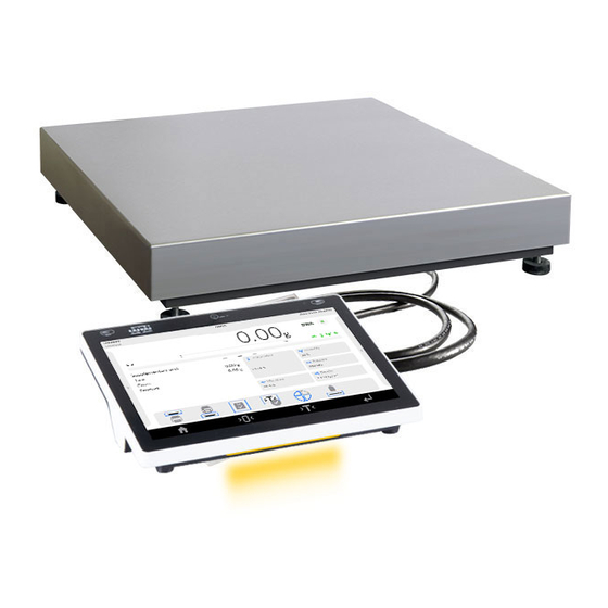
The product must be disposed of when its life ends in accordance with applicable law. 6. STRUCTURE CY10 are single-sensor scales intended to quickly and precisely measure masses up to 300 kg. In single-sensor scales, mass is measured by one mass sensor located in the structure of the platform. -
Page 8: Dimensions
Single-sensor scale components – general view: Single-sensor scale components – general view: 1 - Weighing pan, 2 - Star-piece, 3 – Mass sensor, 4 – Foundation 6.1. Dimensions CY10.D2 scales – dimensions... - Page 9 CY10.F1.K scales – dimensions CY10.C2.K scales – dimensions...
-
Page 10: Description Of Connectors
CY10.C3.K scales – dimensions 6.2. Description of Connectors Reboot or on/off button Left loudspeaker Right loudspeaker USB type-A port USB type-A port... -
Page 11: Installation
Weighing platform cable glands 7. INSTALLATION 7.1. Unpacking and Assembly 7.1.1. CY10.D2 Series Scales A. Remove the scale from the factory box. B. Place the device in the place of use, on the even and hard flooring, away from sources of heat. -
Page 12: Cy10.Xx.k Series Scales
Plug the feeder cable into the mains socket and put the feeder cable plug into the port at the back of the weighing indicator housing. The operating system and RADWAG software loading procedure will initiate in a moment. While the program is being launched, a signal LED light and LED lights at the lower frontal part of the indicator will flash. -
Page 13: Home Page
If the program crashes during operation, reboot it. To do so, press and hold the button in the scale head for about 5 seconds. The program will restart and device will reload. 8. HOME PAGE The home page can be divided into 5 fields: ... -
Page 14: Navigation In The Menu
Information in this field can be freely programmed. Defining method can be found in ‘PUE CY10 indicator software manual’. The on-screen functional buttons are showed below: The scale operator can define on-screen functional buttons. Defining method can be found in „PUE CY10 indicator software manual”. -
Page 15: Return To Weighing Function
Search item in database by name Search item in database by code Print item from database Select variables for printout template Return to previous menu level 9.2. Return to Weighing Function Any changes made in the scale memory are automatically recorded in the menu after going back to the home screen. -
Page 16: Connection Wire Diagrams
Avoid side loads scale, particularly side strokes. 11. CONNECTION WIRE DIAGRAMS Scale – computer wire (RS232) Scale – printer wire (RADWAG, ZEBRA) To assure correct cooperation with peripherals with the use of RS232 ports, use a USB-RS232 converter. -
Page 17: Technical Parameters
‘Scale – Ethernet’ wire is a standard network cable that ends on both sides with RJ45 tip. 12. TECHNICAL PARAMETERS Technical parameters of particular scales are available on the following website: www.radwag.pl. 13. ERROR MESSAGES...
Need help?
Do you have a question about the CY10 and is the answer not in the manual?
Questions and answers