Toro Power Max 826 OXE Operator's Manual
Hide thumbs
Also See for Power Max 826 OXE:
- Operator's manual (32 pages) ,
- Operator's manual (28 pages) ,
- Operator's manual (28 pages)
Table of Contents
Advertisement
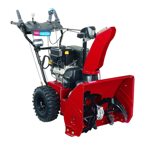
Power Max® 826 OXE Snowthrower
Model No. 38815—Serial No. 400000000 and Up
Introduction
This machine is intended to be used by residential
homeowners. It is designed primarily for removing
snow from paved surfaces, such as driveways and
sidewalks, and other surfaces for traffic on residential
or commercial properties. It is not designed for
removing materials other than snow, nor is it designed
for clearing off gravel surfaces.
Read this information carefully to learn how to operate
and maintain your product properly and to avoid
injury and product damage. You are responsible for
operating the product properly and safely.
You may contact Toro directly at www.Toro.com
for product safety and operation training materials,
accessory information, help finding a dealer, or to
register your product.
Whenever you need service, genuine Toro parts, or
additional information, contact an Authorized Service
Dealer or Toro Customer Service and have the model
and serial numbers of your product ready.
identifies the location of the model and serial numbers
on the product. Write the numbers in the space
provided.
G016493
1. Model and serial number location
Model No.
Serial No.
© 2017—The Toro® Company
8111 Lyndale Avenue South
Bloomington, MN 55420
Figure 1
ST OP
Figure 1
Register at www.Toro.com.
This manual identifies potential hazards and has
safety messages identified by the safety-alert symbol
(Figure
2), which signals a hazard that may cause
serious injury or death if you do not follow the
recommended precautions.
This manual uses 2 words to highlight information.
Important calls attention to special mechanical
information and Note emphasizes general information
worthy of special attention.
1
g016493
Form No. 3415-747 Rev A
Operator's Manual
Figure 2
Safety-alert symbol
Original Instructions (EN)
All Rights Reserved *3415-747* A
Printed in Mexico
g000502
Advertisement
Table of Contents

Related Manuals for Toro Power Max 826 OXE


Summary of Contents for Toro Power Max 826 OXE
-
Page 1: Introduction
Whenever you need service, genuine Toro parts, or additional information, contact an Authorized Service Dealer or Toro Customer Service and have the model and serial numbers of your product ready. Figure 1 identifies the location of the model and serial numbers on the product. -
Page 2: Table Of Contents
Unclogging the Discharge Chute ...... 17 a dealer convenient to you, access our website Operating Tips ..........17 at www.Toro.com or contact our Toro Customer After Operation ............ 18 Care Department at the number(s) listed in your After Operation Safety ........18 Emission Control Warranty Statement. -
Page 3: Figure
Safety General Safety This machine complies with ANSI B71.3 specifications. • Read and understand the contents of this Operator’s Manual before you start the engine. Ensure that everyone using this product knows how to use the product and understands the warnings. -
Page 4: Safety And Instructional Decals
Safety and Instructional Decals Safety decals and instructions are easily visible to the operator and are located near any area of potential danger. Replace any decal that is damaged or missing. decal121-6817 121-6817 1. Cutting dismemberment, impeller and cutting dismemberment, auger hazards—keep bystanders a safe 120-9805 distance away from the snowthrower. - Page 5 decal131-6487 131-6487 1. Engine—shut off 3. Fast 2. Slow decal121-1240 121-1240 Order Part No. 120-7194 1. Traction drive—squeeze the lever to engage; release the 4. Cutting dismemberment hazard, impeller—keep away lever to disengage. from moving parts; remove the ignition key and read the instructions before servicing or performing maintenance.
-
Page 6: Setup
Setup Loose Parts Use the chart below to verify that all parts have been shipped. Procedure Description Qty. Handle bolt Curved washer Install the upper handle. Locknut Install the chute. Carriage bolt Flat washer Hairpin cotter Install the traction-control linkage. Flat washer Carriage bolt Install the chute-control rod. -
Page 7: Installing The Chute
Installing the Chute Installing the Traction-Control Linkage Parts needed for this procedure: Parts needed for this procedure: Carriage bolt Hairpin cotter Flat washer Flat washer Procedure Procedure 1. Place the chute on the frame and align the 1. Insert the lower end of the rod into the lower-link discharge-chute mount to the chute support. -
Page 8: Installing The Chute-Control Rod
4. Shift the speed-selector lever into the R2 position. 5. Rotate the lower-link arm fully upward (counterclockwise) as shown in Figure Installing the Chute-Control Parts needed for this procedure: Carriage bolt g019378 Locknut g019378 Figure 8 Procedure 6. Pull up on the speed-control rod and insert the 1. -
Page 9: Checking The Engine-Oil Level
Checking the Engine-Oil Level No Parts Required Procedure Note: Your machine comes with oil in the engine crankcase. Before starting the engine, check the oil g018885 level and add oil if necessary. g018885 Figure 11 Refer to Checking the Engine-Oil Level (page 20). -
Page 10: Checking The Skids And Scraper
Checking the Skids and Scraper g001011 No Parts Required Figure 14 Procedure The machine should move rearward. If the machine does not move or moves forward, Refer to Checking and Adjusting the Skids and complete the following: Scraper (page 20). A. -
Page 11: Product Overview
Product Overview g004217 Figure 17 1. Snow-cleanout tool (attached to the handle) Operation Before Operation Before Operation Safety g018887 • For electric-start models only: Use extension cords and receptacles as specified in the manual. Thoroughly inspect the electrical cord before plugging it into a power source. -
Page 12: Filling The Fuel Tank
DANGER Fuel is extremely flammable and explosive. A fire or explosion from fuel can burn you and others. • To prevent a static charge from igniting the fuel, place the container and/or machine on the ground before filling, not in a vehicle or on an object. -
Page 13: Starting The Engine
• Never attempt to make any adjustments while the engine is running. • After striking a foreign object, shut off the engine, remove the ignition key (electric-start models only), thoroughly inspect the machine for any damage, and repair the damage before starting and operating the machine. - Page 14 g215361 Figure 24 1. Electric-starter button 3. Recoil-start handle 2. Electric starter plug-in Note: To use the electric starter (electric-start models only), connect a power cord to the plug-in first and then to a power outlet. Use G016501 only a UL-listed, 16-gauge extension cord g016501 recommended for outdoor use that is not longer Figure 22...
-
Page 15: Shutting Off The Engine
Shutting Off the Engine Operating the Traction Drive 1. Move the throttle to the S position, and then to the S position (Figure 25). You can also shut off the engine by pulling the ignition key CAUTION outward to the middle position. If the traction drive is not properly adjusted, the machine may move in the direction opposite of what you intended, causing injury... -
Page 16: Operating The Auger/Impeller Drive
Operating the Quick Stick® Hold the blue trigger cap down to use the Quick Stick to move the discharge chute and the chute deflector. Release the trigger cap to lock the discharge chute and chute deflector into position (Figure 30). g001012 Figure 28 Operating the... -
Page 17: Unclogging The Discharge Chute
Moving the Chute Deflector Operating Tips Hold the blue trigger cap down and move the Quick Stick forward to lower the chute deflector; move it DANGER rearward to raise the chute deflector (Figure 32). When the machine is in operation, the impeller and auger rotate and can injure or amputate hands or feet. -
Page 18: After Operation
After Operation After Operation Safety • Never store the machine with fuel in the fuel tank inside a building where ignition sources are present, such as hot water heaters, space heaters, or clothes dryers. Allow the engine to cool before storing in any enclosure. -
Page 19: Maintenance
• Do not change the governor settings on the engine. • Purchase only genuine Toro replacement parts and accessories. Preparing for Maintenance 1. Move the machine to a level surface. 2. Shut off the engine and wait for all moving parts to stop. -
Page 20: Checking The Engine-Oil Level
Checking the Engine-Oil Checking and Adjusting the Level Skids and Scraper Service Interval: Before each use or daily Service Interval: Yearly—Check the skids and the scraper and adjust them if necessary. Check the skids and the scraper to ensure that the auger does not contact the paved or gravel surface. -
Page 21: Checking And Adjusting The Traction Cable
Checking and Adjusting the Traction Cable Service Interval: After the first 2 hours—Inspect the traction cable and adjust it if necessary. Yearly—Inspect the traction cable and adjust or replace it if necessary. If the machine does not drive in the forward or reverse speeds or it drives when you release the traction lever, adjust the traction cable. -
Page 22: Checking The Auger-Gearbox-Oil Level
3. Loosen or tighten the turnbuckle to adjust the 3. Remove the pipe plug from the gearbox. spring length to 7 cm (2-3/4 inches) as shown 4. Check the oil level in the gearbox. The oil should Figure be 9.5 mm (3/8 inch) below the filler opening. 5. -
Page 23: Lubricating The Hex Shaft
Wait until the engine is cool to replace the and block it so that it cannot fall. spark plug. 3. Remove the back cover (Figure 43). Use a Toro spark plug or equivalent (Champion® RN9YC or NGK BPR6ES). 1. Remove the boot (Figure 44). -
Page 24: Adjusting The Discharge-Chute Latch
Note: Ensure that the ignition wire snaps completely into place on the spark plug. Adjusting the Discharge-Chute Latch If the discharge chute does not lock into the desired position or does not unlock so that you can move it to another position, adjust the discharge-chute latch. -
Page 25: Storage
Storage Preparing the Machine for Storage 1. On the last refueling of the year, add fuel stabilizer to fresh fuel as directed by the engine manufacturer. Important: Do not store fuel longer than that suggested by the fuel-stabilizer manufacturer. 2. Run the engine for 10 minutes to distribute the conditioned fuel through the fuel system. -
Page 26: Troubleshooting
Troubleshooting Problem Possible Cause Corrective Action The electric starter does not turn (electric 1. The power cord is disconnected at the 1. Connect the power cord to the outlet start only). outlet or the machine. and/or the machine. 2. The power cord is worn, corroded, or 2. - Page 27 5. Unclog the discharge chute. 6. The auger/impeller drive belt is loose 6. Install and/or adjust the auger/impeller or is off the pulley. drive belt; refer to www.Toro.com for servicing information or take the machine to an Authorized Service Dealer.
- Page 28 The Way Toro Uses Information Toro may use your personal information to process warranty claims, to contact you in the event of a product recall and for any other purpose which we tell you about. Toro may share your information with Toro's affiliates, dealers or other business partners in connection with any of these activities. We will not sell your personal information to any other company.
Need help?
Do you have a question about the Power Max 826 OXE and is the answer not in the manual?
Questions and answers