Sign In
Upload
Download
Table of Contents
Contents
Add to my manuals
Delete from my manuals
Share
URL of this page:
HTML Link:
Bookmark this page
Add
Manual will be automatically added to "My Manuals"
Print this page
×
Bookmark added
×
Added to my manuals
Manuals
Brands
Teledyne Manuals
Measuring Instruments
T3CP30-50
Manual
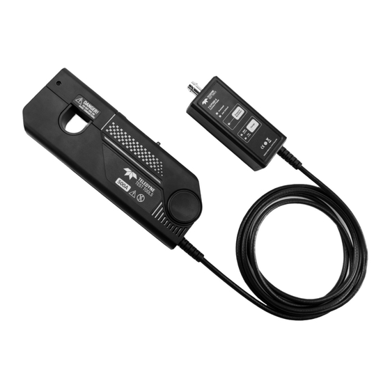
Teledyne T3CP30-50 Manual
Current probes
Hide thumbs
1
2
Table Of Contents
3
4
5
6
7
8
9
10
11
12
13
14
15
16
17
18
19
20
21
22
23
24
page
of
24
Go
/
24
Contents
Table of Contents
Bookmarks
Table of Contents
Table of Contents
General Safety Summary
Safety Terms and Symbols
Product Overview
Key Features
Applications
Product Description
Making Measurements
Safe Probing
Operating Method
Preparation before Testing
Degaussing and Zero Setting
Measuring Method
Frequently Asked Questions and Tips
Specifications
Certifications
Safety Compliance
Environmental Compliance
Warranty
Advertisement
Quick Links
Download this manual
T3CP Current Probes Manual
DC/AC Current Probes
Table of
Contents
Previous
Page
Next
Page
1
2
3
4
5
Advertisement
Table of Contents
Need help?
Do you have a question about the T3CP30-50 and is the answer not in the manual?
Ask a question
Questions and answers
Related Manuals for Teledyne T3CP30-50
Measuring Instruments Teledyne T300 Operation Manual
Carbon monoxide analyzer (426 pages)
Measuring Instruments Teledyne T300 Operation Manual
Carbon monoxide analyzer (401 pages)
Measuring Instruments Teledyne T360 Operation Manual
Carbon dioxide analyzer (358 pages)
Measuring Instruments Teledyne T3SP Series Operator's Manual
Time domain reflectometer (70 pages)
Measuring Instruments Teledyne T3SP Series Operator's Manual
Time domain reflectometer (103 pages)
Measuring Instruments Teledyne T3LCR1002 User Manual
Precision lcr meters (147 pages)
Measuring Instruments Teledyne T3LCR1002 Quick Start Manual
Precision lcr meters (21 pages)
Measuring Instruments Teledyne Everywhereyoulook T3PM1100 User Manual
Digital power meter (227 pages)
Measuring Instruments Teledyne T3PM1100 User Manual
Digital power meter (227 pages)
Measuring Instruments Teledyne T3MIL50 User Manual
D.c. milli-ohm meters (155 pages)
Measuring Instruments Teledyne T3PM1006 User Manual
Digital power meter (121 pages)
Measuring Instruments Teledyne T3CP30-100 Manual
Current probes (24 pages)
Measuring Instruments Teledyne T3VNA Use & Care Manual
Vector network analyzers (132 pages)
Measuring Instruments Teledyne T3LVD Manual
Voltage probe (16 pages)
Measuring Instruments Teledyne T3SA3000-NFP User Manual
Near field probe (8 pages)
Measuring Instruments Teledyne Everywhereyoulook T3AWG6K Series Operator's Manual
(110 pages)
This manual is also suitable for:
T3cp30-100
T3cp50-50
T3cp150-12
T3cp500-5
Table of Contents
Print
Rename the bookmark
Delete bookmark?
Delete from my manuals?
Login
Sign In
OR
Sign in with Facebook
Sign in with Google
Upload manual
Upload from disk
Upload from URL


Need help?
Do you have a question about the T3CP30-50 and is the answer not in the manual?
Questions and answers