
Related Manuals for Beijer Electronics JetNet 6228G Series


Summary of Contents for Beijer Electronics JetNet 6228G Series
- Page 1 Industrial 28-port L2 Managed Ethernet Switch JetNet 6228G Series Installation Guide Page 1 of (44) JetNet 6228G Series Installation Guide...
- Page 2 JetNet 6228G Installation Guide DOCUMENT CHANGE SUMMARY JetNet 6228G Series Installation Guide Page 2 of (44)
- Page 3 (such as translation, transformation, or adaptation) without written permission from Beijer Electronics and/or its affiliates ("Beijer"). BEIJER reserves the right to revise or change this content from time to time without obligation on the part of BEIJER to provide notification of such revision or change.
- Page 4 Trademarks ⚫ BEIJER, the BEIJER logo, and JetNet are trademarks of Beijer Electronics and/or its affiliates. Wi-Fi Alliance, Wi-Fi, the Wi-Fi logo, the Wi-Fi CERTIFIED logo, Wi-Fi Protected Access (WPA), the Wi-Fi Protected Setup logo, and WMM are registered trademarks of Wi-Fi Alliance. Wi-Fi Protected Setup™, Wi-Fi Multimedia™, and WPA2™...
-
Page 5: Table Of Contents
2.3. Package Contents .................. 22 2.4. Validating Operational Function ..............22 2.5. Installing the Switch ................22 Installation Requirements ............... 22 Installing Guidelines ................23 Installing on a Rack ................24 JetNet 6228G Series Installation Guide Page 5 of (44) - Page 6 Connecting DC Power Inputs ..............38 Power Supply Specifications ..............40 Connecting Digital Output Wires ............... 41 3.1. Before You Begin .................. 42 3.2. Accessing the Web Interface ..............42 3.3. Changing Passwords ................43 JetNet 6228G Series Installation Guide Page 6 of (44)
- Page 7 In no event will Beijer Electronics be responsible or liable for indirect or consequential • damages resulting from the use or application of this equipment.
-
Page 8: Safety Instruction
The modules are equipped with electronic components that may be destroyed by electrostatic discharge. When handling the modules, ensure that the environment (persons, workplace and packing) is well grounded. Avoid touching conductive components, M-bus and Hot swap-bus pin. JetNet 6228G Series Installation Guide Page 8 of (44) -
Page 9: I.iii. Certification
JetNet 6228G Installation Guide I.III. Certification Note! For specific information relating to certification of this module type, see the separate certification document summary. The following certification information applies to JetNet 6228G series models: CE compliance ⚫ FCC compliance ⚫ JetNet 6228G Series Installation Guide... -
Page 10: Introduction
Moreover, the JetNet 6228G series supports harsh environments at -40°C to 75°C and is designed with an industrial EMC grade to ensure proper operation. Also, the JetNet 6228G series has various cyber security and cyber redundancy features, as well as isolated redundant power supplies. -
Page 11: Switch Models
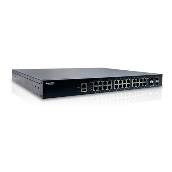
JetNet 6228G Installation Guide Switch Models The JetNet 6228G series is available in the following models: JetNet 6228G-4F-AC, JetNet 6228G-4F-2DC, and JetNet 6228G-4F-AC-2DC. The following figures depict the models. Switch Model Description Image JetNet 6228G-4F-AC Industrial 28-port Full Gigabit with 4-... -
Page 12: Technical Specifications
IEEE 802.1p class of service Configuration, • SNMP V1/V2c/V3 with SNMP Trap (4 Trap Stations), monitoring interface RMON Group 1 • Local RJ-45/RS-232 connector with Cisco like command • USB Firmware upgrade JetNet 6228G Series Installation Guide Page 12 of (44) - Page 13 Flexible, scalable ring technology, compatibility, and Redundancy easy configurable: Border Switch and Member Switch Rapid Spanning Tree IEEE 802.1D-2004 Rapid Spanning Tree Protocol. Compatible with Legacy Spanning Tree and IEEE 802.1w JetNet 6228G Series Installation Guide Page 13 of (44)
- Page 14 Shock IEC 60068-2-27 Free Fall IEC 60068-2-32 MTBF 570,639 hrs Warranty 5 Years * Maximum power consumption values are measured under a 100% load test and should be used as estimates. JetNet 6228G Series Installation Guide Page 14 of (44)
-
Page 15: Front Panel
JetNet 6228G Installation Guide 1.3. Front Panel Described in this section are the front panel components of the JetNet 6228G series switches. JetNet 6228G-4F-AC The LEDs and ports are located on the front panel of the switch as illustrated in the following illustrations. -
Page 16: Jetnet 6228G-4F-2Dc
Gbps on Cat 5e cables. System LEDs See Front Panel LEDs on page 18 for further details. USB Type A port USB ports connect to USB devices for restoring firmware images. JetNet 6228G Series Installation Guide Page 16 of (44) -
Page 17: Jetnet 6228G-4F-Ac-2Dc
Gbps on Cat 5e cables. System LEDs See Front Panel LEDs on page 18 for further details. USB Type A port USB ports connect to USB devices for restoring firmware images. JetNet 6228G Series Installation Guide Page 17 of (44) -
Page 18: Front Panel Leds
JetNet 6228G Installation Guide Front Panel LEDs The system LEDs are used to monitor the switch activity and performance. Figure 3 Front Panel LEDs of 28-Port JetNet 6228G Series No. Item Description Power LED AC: Available only on AC models. -
Page 19: Rear Panel
JetNet 6228G Installation Guide 1.4. Rear Panel The power inputs and relay connectors are located on the rear panel of the switch as illustrated in the following illustrations. Figure 3 Rear Panel of 28-Port JetNet 6228G Series No. Item Description AC power socket AC socket available only on AC models. -
Page 20: Dimensions
The power inputs and relay connectors are located on the rear panel of the switch as illustrated in the following illustrations. Note! For demonstration purposes, the Dimensions view illustrates a single JetNet 6288G model. Figure 3 Dimensions of 28-Port JetNet 6228G Series JetNet 6228G Series Installation Guide Page 20 of (44) -
Page 21: Electrical Safety Information
5VA, V2, V1, V0 (or equivalent) if nonmetallic. Enclosures must only be accessible with a tool for their interior. The subsequent sections of this publication may contain information on specific enclosure-type ratings that must be JetNet 6228G Series Installation Guide Page 21 of (44) -
Page 22: Package Contents
2.3. Package Contents After unpacking the device, validate the contents to ensure you have received all the included components. • Jetnet 6228G series: JetNet 6228G-4F-AC, JetNet 6228G-4F-2DC, or JetNet 6228G-4F-AC-2DC • AC Power Cord (Dependent on country or region) •... -
Page 23: Installing Guidelines
(e.g., where flakes of metal from construction activities are not present). • It is important that the humidity around the switch does not exceed 90%. JetNet 6228G Series Installation Guide Page 23 of (44) -
Page 24: Installing On A Rack
Before mounting or servicing the unit in the rack, install any stabilizing devices provided with the rack. The following figure depicts the standard 19-inch brackets included with the device. Figure 3 Standard 19-inch Rail Mounting Brackets JetNet 6228G Series Installation Guide Page 24 of (44) -
Page 25: Connecting The Rack-Mount Brackets
3 Slide the switch and slide it in until it is flush in the rack. Secure the switch in the rack with the provided mounting screws. 4 Slide the switch into the rack, see the following figure. 5 Use the supplied screws to attach the switch to the rack. JetNet 6228G Series Installation Guide Page 25 of (44) -
Page 26: Connecting Ethernet Cables
To maximize performance, choose one of these methods for configuring the Ethernet ports: • Allow the ports to negotiate both speed and duplex. • Ensure that both ends of the connection are set to the same interface speed and duplex parameters. JetNet 6228G Series Installation Guide Page 26 of (44) -
Page 27: Ethernet Cable Wiring
Note!! Ethernet cables use pins 1, 2, 3, and 6 of an 8-pin RJ-45 connector. The signals of these pins are converted by the automatic MDI-X function, as shown in the table below: Ethernet Cable Pin Definition Pin MDI-X Signals MDI Signals JetNet 6228G Series Installation Guide Page 27 of (44) -
Page 28: Data And Power Ports
Description RX + and V port - RX - and V port - TX + and V port + TX – and V port + 4, 5, 7, 8 Not applicable JetNet 6228G Series Installation Guide Page 28 of (44) -
Page 29: Connecting A Serial Cable
Figure 3 D-sub 9-pin Position DB9 Connector RJ45 Connector 1 Orange / White 2 Orange 3 Green / White 4 Blue 5 Blue / White 6 Green 7 Brown / White 8 Brown JetNet 6228G Series Installation Guide Page 29 of (44) -
Page 30: Connecting And Disconnecting Sfp Modules
Optical signals do not require a circuit to transmit data like electrical signals. In order to achieve full-duplex transmission, one of the optical lines transmits data from device I to device II, and the JetNet 6228G Series Installation Guide Page 30 of (44) - Page 31 4 Make sure the triangular marking (TX and RX) on the slot is aligned with the bottom of the transceiver. 5 Once the SFP transceiver has been inserted into the slot, push it in until it snaps in place. JetNet 6228G Series Installation Guide Page 31 of (44)
- Page 32 If the LED is off, ensure the target device is powered up. Otherwise, check the cable and cable connection for any issues. 10 Insert the fiber optic cable into the transceiver. The cable snaps in place when correctly connected. JetNet 6228G Series Installation Guide Page 32 of (44)
-
Page 33: Disconnecting An 1000Base-T Sfp Module
Pull the optic cable out to release it from the transceiver. Figure 3 Disengaging the Optic Cable from the Module 2 Hold the handle on the transceiver to pull the module out of the port. JetNet 6228G Series Installation Guide Page 33 of (44) - Page 34 Figure 3 Disconnecting an SFP Module Figure 3 Disconnecting an SFP Module The rubber plug should be replaced if the transceiver is not installed. Rubber plugs prevent dust contamination of hardware. JetNet 6228G Series Installation Guide Page 34 of (44)
-
Page 35: Connecting Power Inputs
• Electrically similar wiring should not be bundled together. • Ensure that inputs and outputs are wired separately. JetNet 6228G Series Installation Guide Page 35 of (44) -
Page 36: Grounding The Device
3 Remove the ground screw from the rear panel of the switch. 4 Install the lug and the wire assembly over the grounding hole and secure with the ground-lug screw (60 in-lb). JetNet 6228G Series Installation Guide Page 36 of (44) -
Page 37: Connecting Ac Power Input
AC power supply. Connect the supplied power cord to the AC power input slot. The AC power input range is as follows: 100-240VAC. Figure 3 Connecting an AC Power Input JetNet 6228G Series Installation Guide Page 37 of (44) -
Page 38: Connecting Dc Power Inputs
3 Use a Phillips screwdriver to loosen the screws on the terminal block. 4 Identify the positive (red) and negative (black) wire lugs and insert them to the respective RTN (+) and NEG (-) terminals. JetNet 6228G Series Installation Guide Page 38 of (44) - Page 39 5 After connecting the DC wire lugs, tighten the screws on the terminal block. DC1 and DC2 support polarity reverse protection functions. Figure 3 Wiring the DC Power Inputs 6 Remove the temporary labels on the cables and replace them with formal labels. JetNet 6228G Series Installation Guide Page 39 of (44)
-
Page 40: Power Supply Specifications
Rating Consumption All Ethernet Ports 18 VDC 18 VDC 75 VDC 10A (T) DC: 19W 75 VDC AC: 35W HI (110/230 VAC, 100 VAC 240 VAC 0.3A 15A (T) 47~63 Hz) JetNet 6228G Series Installation Guide Page 40 of (44) -
Page 41: Connecting Digital Output Wires
The two wires attached to the fault contacts form an open circuit when a user-configured event is triggered. Fault circuits remain closed if a user-configured event does not occur. Connect the Digital Output (DO): Figure 3 Wiring the DC Power Inputs JetNet 6228G Series Installation Guide Page 41 of (44) -
Page 42: Before You Begin
JetNet 6228G Installation Guide Chapter 3. Configuring the JetNet 6228G Series Switches This chapter describes how to log in to a JetNet 6228G switch for the first time. There following information demonstrates how to access the switch’s configuration settings through the web-based interface. -
Page 43: Changing Passwords
3 Under User Account, select the admin profile and click Edit. Figure 2 System Management > User Management 4 The detailed user profile menu displays. In the Password field, enter the new password. JetNet 6228G Series Installation Guide Page 43 of (44) - Page 44 5 In the Confirm password field, enter the new password to confirm it and click Confirm. Figure 3 Confirming a New Password 6 Under the main menu tree, navigate to Save Configuration. The Save Configuration screen displays. 7 Click Apply to save the new password setting. JetNet 6228G Series Installation Guide Page 44 of (44)
Need help?
Do you have a question about the JetNet 6228G Series and is the answer not in the manual?
Questions and answers