Table of Contents
Advertisement
Quick Links
A Beijer Electronics Group Company
JetNet 6528Gf Series Industrial 28G Full Gigabit Managed Ethernet Switch
Quick Installation Guide V1.1
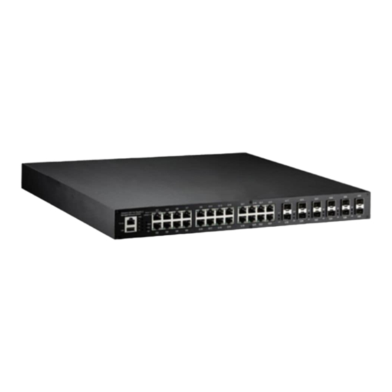
Overview
e JetNet 6528Gf Series is a 19-inch Industrial 28G Full Gigabit Managed Ethernet Switch
equipped with 24 100/1000TX, 8 100/1000 RJ-45/SFP combo ports, 4 GbE SFP ports.
Model Name
Description
24 100/1000TX, 8 100/1000 RJ-45/SFP combo ports, 4 GbE SFP ports,
JetNet 6528Gf-AC
Ind. full Gigabit Managed Ethernet Switch, -40~75°C, AC power
24 100/1000TX, 8 100/1000 RJ-45/SFP combo ports, 4 GbE SFP ports,
JetNet 6528Gf-2AC
Ind. full Gigabit Managed Ethernet Switch, -40~75°C, dual AC power
24 100/1000TX, 8 100/1000 RJ-45/SFP combo ports, 4 GbE SFP ports,
JetNet 6528Gf-AC-DC24
Ind. full Gigabit Managed Ethernet Switch, -40~75°C, AC and DC power
24 100/1000TX, 8 100/1000 RJ-45/SFP combo ports, 4 GbE SFP ports,
JetNet 6528Gf-2DC24/48
Ind. full Gigabit Managed Ethernet Switch, -40~75°C, dual DC power
Package Check List
e Rack Mount Managed Ethernet Switch
Console cable
Rack Mount kit
Power Cord (Depend on Country, JetNet 6528Gf-2DC24/48 no Power Cord)
QIG
Interface Introduction
Dimension
JetNet 6528Gf Industrial 28G Full Gigabit Managed Ethernet Switch dimension (W x H x
D) is 44mm(H) x 438mm (W) x 375mm (D).
Industrial 28G Full Gigabit
G1
G3
G5
G7
G9
G11
G13
G15
G17
G19
G21
G23
G17
G19
G21
G23
Managed Ethernet Switch
Speed
LNK/ACT
PWR
1
Console
2
G17
G19
G21
G23
G25
Alarm
3
USB
R.S.
4
Sys
G2
G4
G6
G8
G10
G12
G14
G16
G18
G20
G22
G24
G18
G18
G20
G20
G22
G22
G24
G24
G26
Front-Panel Components
e front panel includes RJ-45 based RS-232 console port, USB port, System & port LEDs,
Gigabit Ethernet port Interfaces and Gigabit combo port Interfaces.
Industrial 28G Full Gigabit
Managed Ethernet Switch
Console
USB
Back-Panel Components
e back panel of the JetNet 6528Gf Industrial 28G Full Gigabit Managed Ethernet Switch
consists of AC power input, DC power input and relay output depend on di erent Model.
JetNet 6528Gf-2AC:
90-264VAC, 50-60Hz
JetNet 6528Gf-2DC24/48:
Model Name
JetNet 6528Gf-AC
JetNet 6528Gf-2AC
JetNet 6528Gf-AC-DC24
JetNet 6528Gf-2DC24/48
LED Indicators
Industrial 28G Full Gigabit
Managed Ethernet Switch
Console
USB
LED
PWR
Alarm
R.S.
Sys
G1-G24 Copper
LNK/ACT
G1-G24 Copper
Speed
G25
G27
G17-G28 SFP
G27
G26
G28
G28
LNK/ACT
G1
G3
G5
G7
G9
G11
G13
G15
G17
G19
G21
G23
G17
G19
Speed
LNK/ACT
PWR
1
2
G17
G19
G21
Alarm
3
R.S.
4
Sys
G2
G4
G6
G8
G10
G12
G14
G16
G18
G20
G22
G24
G18
G18
G20
G20
G22
PWR1
PWR2
90-264VAC, 50-60Hz
PWR3
18-36VDC
Back-Panel Components
1 AC power inputs and 1 relay output.
2 AC power inputs and 1 relay output.
1 AC power inputs, 1 DC power inputs and 1 relay output.
2 DC power inputs and 1 relay output.
G1
G3
G25
Speed
LNK/ACT
PWR
1
2
G25
Alarm
3
R.S.
4
Sys
G26
G2
G4
G26
Color
Function
Green
Power (AC1, AC2, DC1, DC2) on
Power failure, port failure, ping failure,
Red
login failure, RSR topology change
Lit Green
MSR in normal state
Lit Yellow
MSR in abnormal state
Not Lit
MSR function not active
Incorrect configuration of MSR, ex. ring not
Flashes Green
connected to ring port
Flashes
The break has been detected to be local to
Yellow
one of the ports
Green
System on
10/100/1000 RJ-45 Link
Lit Green
Flashes Green
10/100/1000 RJ-45 Activity
Yellow on
1000Mbps
10/100Mbps
Yellow off
Lit Green
Link
Flashes Green
Activity
Installation
Mount the Switch to 19'' rack
1. Attach the brackets to the device by using the
G21
G23
G25
G27
screws provided in the Rack Mount kit.
G23
G25
G27
2. Mount the device in the 19'' rack by using four
G22
G24
G24
G26
G26
G28
G28
rack-mounting screws provided by the rack
manufacturer.
3. When installing multiple switches, mount them in
the rack one below the other.
Note: Check if the rack environment temperature conforms to the speci ed operating
temperature range. Do not place any equipment on top of the switch and please properly
1A@24V
grounded.
PWR4
1A@24V
Power the unit and connect to network Cable
AC Power Input: connect the attached power cord to the AC power input connector, the
G27
available AC power input is range from 90-264VAC.
DC Power Input: the suggested power input is 24VDC/48 VDC, the available range is from
G27
18-36VDC/ 36-75VDC.
Follow below steps to wire JetNet 6528Gf redundant DC power inputs.
G28
G28
1. Insert positive and negative wires into V+ and V- contacts respectively of the terminal
block connector.
2. Tighten the wire-clamp screws to prevent DC wires from being loosened.
3. DC1 and DC2 support polarity reverse protection functions.
Wiring Digital Output
JetNet 6528Gf series provides 1 digital output, also known as relay output.
contacts are energized (open) for normal operation and will close for fault conditions.
fault conditions include power failure, Ethernet port link break or other pre-de ned events
which can be con gured in JetNet 6528Gf UI.
Wiring Earth Ground
To ensure the system will not be damaged by noise or any electrical shock, we suggest you to
make exact connection with JetNet 6528Gf with earth ground.
For AC input, the 3 pin include V+, V- and GND.
earth ground.
For DC input, loosen the earth ground screw by screw drive; then tighten the screw after
earth ground wire is connected.
e relay
e
e GND pin must be connected to the
Advertisement
Table of Contents

Related Manuals for Beijer Electronics Korenix JetNet 6528Gf Series


Summary of Contents for Beijer Electronics Korenix JetNet 6528Gf Series
- Page 1 Mount the Switch to 19’’ rack Gigabit Ethernet port Interfaces and Gigabit combo port Interfaces. A Beijer Electronics Group Company 1. Attach the brackets to the device by using the JetNet 6528Gf Series Industrial 28G Full Gigabit Managed Ethernet Switch...
- Page 2 Granted Invention: I 321415 Granted Invention: I 344766 KoreCARE is Korenix Technology's global service center, where our professional sta s are (A Beijer Electronics Group Company) connector to the console port of the JetNet 6528Gf. Granted Invention: I 346480 Granted Invention: I 356616 ready to solve your problems at any time.
Need help?
Do you have a question about the Korenix JetNet 6528Gf Series and is the answer not in the manual?
Questions and answers