Rockwell Automation Allen-Bradley 2090 Series Installation Instructions Manual
Circular-din connector kits, flange kits, and crimp tools
Hide thumbs
Also See for Allen-Bradley 2090 Series:
- Installation instructions manual (12 pages) ,
- Installation instructions manual (12 pages) ,
- Installation instructions manual (14 pages)
Table of Contents
Advertisement
Quick Links
Installation Instructions
2090-Series Circular-DIN Connector Kits,
Flange Kits, and Crimp Tools
2090-KFBM4-CAAA, 2090-KPBM4-12AA, 2090-KPBM4-06AA, 2090-KFBM7-CAAA,
2090-KPBM7-12AA, 2090-KPBM7-06AA, 2090-KFBE7-CAAA, 2090-KPBE7-12AA, 2090-KPBE7-06AA,
2090-KFB47-CF, 2090-KPB47-12CF, 2090-KPB47-06CF, 2090-TCR47-M23, 2090-TCR47-M40
About The Connector Kits,
Flange Kits, and Crimp
Tools
Topic
About The Connector Kits, Flange Kits, and Crimp Tools
Important User Information
Before You Begin
Catalog Number Descriptions
Hand Crimp Tool
8-point Indent Crimp Tool with Digital Display
Type 623 Plug (solder version)
Type 923 Plug (9-pin, crimp version)
Type 940 Plug (8-pin, crimp version)
Type 623 Extension (solder version)
Type 923 Extension (9-pin, crimp version)
Type 940 Extension (8-pin, crimp version)
Two-part Flange (hinged, metal version, CF)
Two-part Flange (hinged, metal version, 12CF)
Two-part Flange (hinged, metal version, 06CF)
Additional Resources
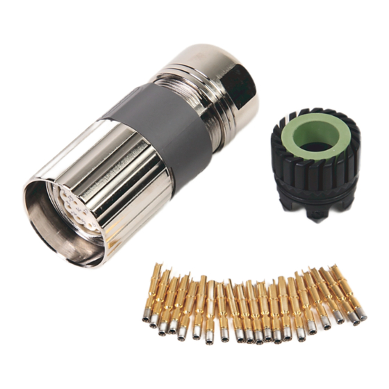
These 2090-series kits and crimp tools are used for assembling a wide variety of
motor/actuator cables with rugged DIN connectors for connecting motion
control systems.
Installation instructions from the manufacturer were included in the shipping
box with the respective kit or crimp tool. This collective installation instruction
includes additional information.
Page
1
2
2
4
5
8
22
23
24
25
26
27
28
29
30
31
Advertisement
Table of Contents

Related Manuals for Rockwell Automation Allen-Bradley 2090 Series


Summary of Contents for Rockwell Automation Allen-Bradley 2090 Series
- Page 1 Installation Instructions 2090-Series Circular-DIN Connector Kits, Flange Kits, and Crimp Tools 2090-KFBM4-CAAA, 2090-KPBM4-12AA, 2090-KPBM4-06AA, 2090-KFBM7-CAAA, 2090-KPBM7-12AA, 2090-KPBM7-06AA, 2090-KFBE7-CAAA, 2090-KPBE7-12AA, 2090-KPBE7-06AA, 2090-KFB47-CF, 2090-KPB47-12CF, 2090-KPB47-06CF, 2090-TCR47-M23, 2090-TCR47-M40 Topic Page About The Connector Kits, Flange Kits, and Crimp Tools Important User Information Before You Begin Catalog Number Descriptions Hand Crimp Tool 8-point Indent Crimp Tool with Digital Display...
-
Page 2: Important User Information
In no event will Rockwell Automation, Inc., be responsible or liable for indirect or consequential damages resulting from the use or application of this equipment. -
Page 3: Before You Begin
If you temporarily coil a power cable, you must also derate the cable to meet local code or follow a authoritative directive, such as Engineering Section 310.15(C) of the NEC Handbook. Rockwell Automation Publication 2090-IN042A-EN-P - May 2011... - Page 4 Two-part flange (hinged, metal version, CF) 2090-KPB47-12CF Cable flange for (threaded and SpeedTec) power connectors Two-part flange (hinged, metal version, 12CF) 2090-KPB47-06CF Cable flange for (threaded and SpeedTec) power connector Two-part flange (hinged, metal version, 06CF) Rockwell Automation Publication 2090-IN042A-EN-P - May 2011...
- Page 5 No-go-check 1. Leave the crimp tool on setting 4 and close the handles. 2. Insert no-go-gauge (red) into the crimp indenters. The no-go-gauge may pass partially through the indenters, but not completely. Rockwell Automation Publication 2090-IN042A-EN-P - May 2011...
- Page 6 4. Remove the wire and contact from the positioning insert. Perform a pull test according to BS EN 60352-2, Table 4, for the first IMPORTANT crimp, and periodically throughout multiple crimpings. Rockwell Automation Publication 2090-IN042A-EN-P - May 2011...
-
Page 7: Maintenance
(4) For positioning inserts with two color codes, match the color code to the wire size. (5) Match the wire size and crimp value to an available contact type to determine the locator version. The crimp values are labeled on the crimp setting dial. Rockwell Automation Publication 2090-IN042A-EN-P - May 2011... - Page 8 ATTENTION: Understand the crimp tool and how it works. Use the crimp tool only for crimping the contacts included in the 2090-series kits. Misuse may cause personal injury. Rockwell Automation Publication 2090-IN042A-EN-P - May 2011...
- Page 9 Before the first use of the crimp tool, you must install a locator and calibrate the crimp tool. • To install the locator, see Installing a Locator on page • To calibrate the crimp tool, see Calibrating the Crimp Tool on page Rockwell Automation Publication 2090-IN042A-EN-P - May 2011...
- Page 10 2. Insert the other Allen wrench in the center of the locator and turn counterclockwise to lift the locator off the threaded post. 3. See Installing a Locator on page 10 to install a different locator. Rockwell Automation Publication 2090-IN042A-EN-P - May 2011...
- Page 11 5. Turn the adjustment wheel counterclockwise (towards the +) to open the crimp indenters to the size of the 2 mm calibration gauge. 6. Place the 2 mm calibration gauge into the crimp indenters. Insert 2 mm Calibration Gauge Into the Indenters Rockwell Automation Publication 2090-IN042A-EN-P - May 2011...
- Page 12 The crimp tool is now calibrated and ready for use. If code E1 displays in the digital display, the calibration was not IMPORTANT successful. Repeat the procedure for calibrating the crimp tool until 2.00 mm shows on the digital display. Rockwell Automation Publication 2090-IN042A-EN-P - May 2011...
- Page 13 Display modes are listed in the flow chart below. Press the Mode push button with the 2 mm calibration gauge to advance to the next setting. MIL Selector Positions Standard Metric Display US/Imperial Display (Eight positions per MIL-22520) (mm) (inch) Back to Default Display Rockwell Automation Publication 2090-IN042A-EN-P - May 2011...
- Page 14 OK. – If the calibration gauge cannot be inserted, or can be inserted but feels loose and has play, the crimp tool must be calibrated. See Calibrating the Crimp Tool on page Rockwell Automation Publication 2090-IN042A-EN-P - May 2011...
- Page 15 See Table 2 on page 20 to determine the correct locator selection. 6. Turn the locator to align the desired locator cartridge with the crimp indenters, then press in the locator cartridge until it snaps into place. Rockwell Automation Publication 2090-IN042A-EN-P - May 2011...
- Page 16 1. Insert the wire into the contact (actual contacts will vary). 2. Feed the contact and wire as far as possible through the indenters to the stop in the locator cartridge. The locator cartridge provides for the exact positioning of the contact. Rockwell Automation Publication 2090-IN042A-EN-P - May 2011...
- Page 17 4. Remove the wire and contact from the locator cartridge. Perform a pull test according to BS EN 60352-2, Table 4, for the first IMPORTANT crimp, and periodically throughout multiple crimpings. Rockwell Automation Publication 2090-IN042A-EN-P - May 2011...
-
Page 18: Changing The Battery
We strongly recommend the following: IMPORTANT • Do not use any rinsing solutions. • Do not lubricate. • Do not try to repair. • Do not disassemble. Rockwell Automation Publication 2090-IN042A-EN-P - May 2011... -
Page 19: Troubleshooting
2. Use a screwdriver to press the ratchet gear away from the catch until it unlocks. Do not crimp materials or contacts that are not designated for use with the crimp tool. Rockwell Automation Publication 2090-IN042A-EN-P - May 2011... - Page 20 (3) The contact type determines which locator cartridge to use. Match the contact type number to the locator cartridge number. (4) Match the wire size and crimp value to an available contact type to determine the locator cartridge. The crimp values are shown in MIL/mm values. Rockwell Automation Publication 2090-IN042A-EN-P - May 2011...
Need help?
Do you have a question about the Allen-Bradley 2090 Series and is the answer not in the manual?
Questions and answers